Cooling fan for reinforcing diversion cooling

A cooling fan, diversion cooling technology, applied to the components of the pumping device for elastic fluid, non-variable displacement pump, pump device, etc., can solve the impact of the hub, reduce the service life, reduce the fan efficiency and fatigue resistance Impact strength and other issues to achieve the effect of increasing flow rate, reducing noise, and enhancing heat exchange capacity

Inactive Publication Date: 2011-06-08
WARNER SHENGLONG NINGBO CO LTD
View PDF0 Cites 7 Cited by
  • Summary
  • Abstract
  • Description
  • Claims
  • Application Information

AI Technical Summary

Problems solved by technology

Its defect is that there is a vortex when it is working. Since the vortex wind cannot be evacuated immediately, a turbulent flow is formed in the annular hub, which produces irregular impact on the hub, reduces the efficiency of the fan and the fatigue impact strength, and shortens the service life. The design of the ring hub prevents the head-on wind from radiating out to the surroundings for effective cooling, and further improvement is needed

Method used


Image

  • Cooling fan for reinforcing diversion cooling
  • Cooling fan for reinforcing diversion cooling
  • Cooling fan for reinforcing diversion cooling

Examples


Embodiment Construction

[0015] The present invention will be further described in detail below in conjunction with the accompanying drawings and embodiments.

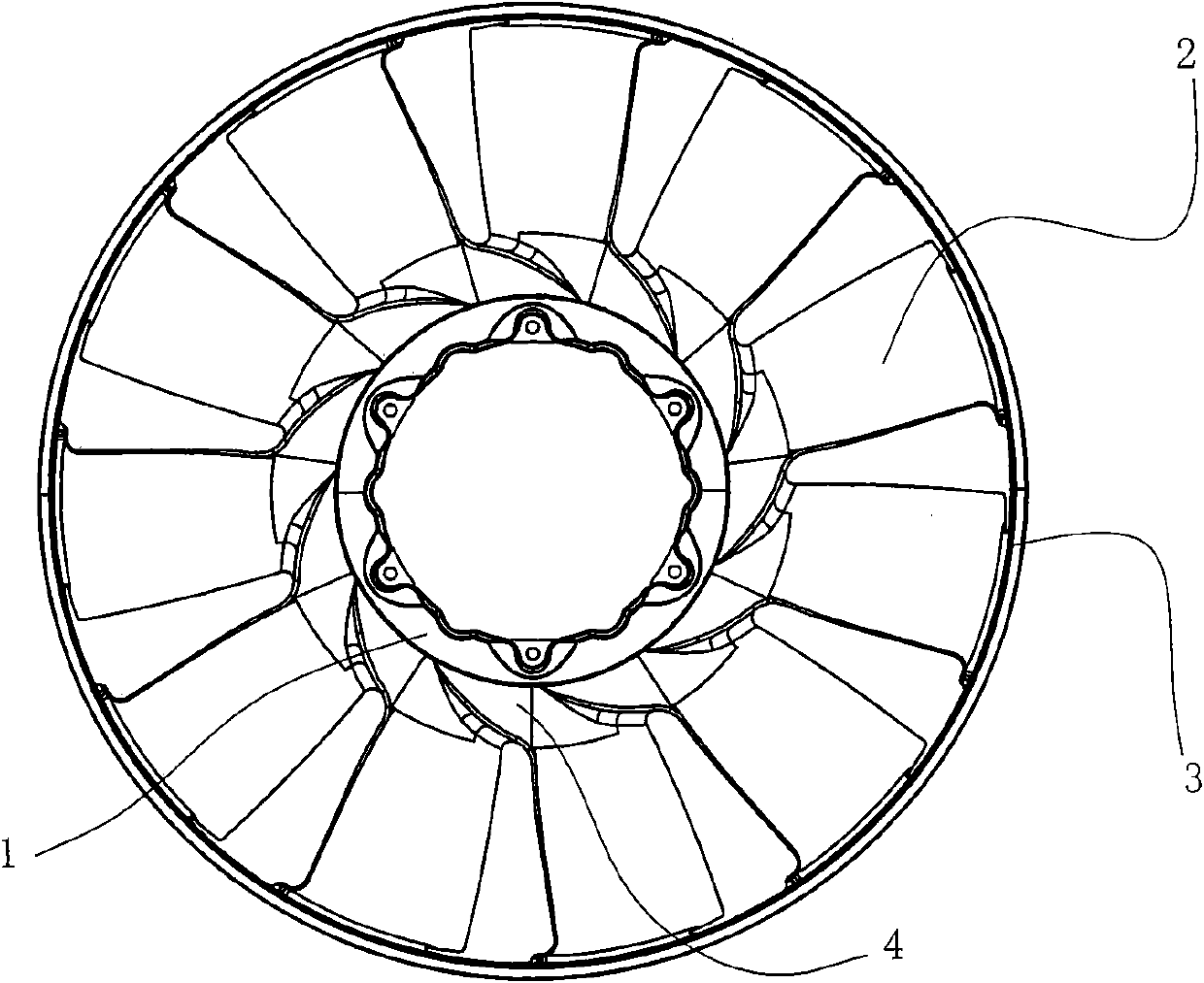
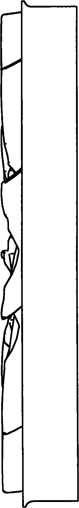
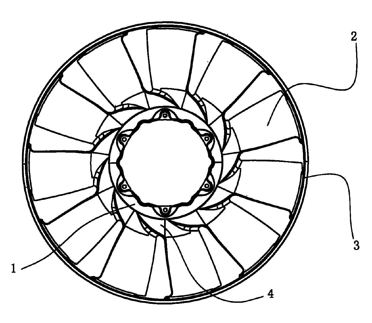
[0016] As shown in the figure, the fan with spiral reinforced diversion cooling new hub design, which at least includes a hub 1, fan blades 2 and guide ring 3, the hub 1 is surrounded by spiral ribs 4, the above fan blades 2 The outer top is connected with the deflector ring 3, and the inner bottom of the fan blade 2 is connected with the rib 4. The traditional hub is a ring design, and the bottom of the fan blade of the traditional fan is directly connected with the ring surface. Due to its structural limitations , so that the head-on wind cannot radiate to the surroundings for effective cooling; the above-mentioned spiral ribs 4 are arranged equidistantly with involutes, which effectively evacuates the head-on wind to the surroundings, and the blades enter the cooling, which can make the cooling The effect is increased by 12% to 14%, and the...


PUM


Abstract

The invention discloses a cooling fan for reinforcing diversion cooling. The cooling fan comprises a hub, fan blades and a diversion ring, wherein the fan blades are connected with the diversion ring. The cooling fan is characterized in that: the periphery of the hub is provided with spiral reinforcing ribs; the spiral reinforcing ribs are connected with the bottoms of the fan blades and are distributed at equal intervals along an involute; the direction of the involute corresponds to the rotation direction of the fan; and in the involute, x and y in a parameter equation can be exchanged along with the rotation direction of the fan by the parameter equation under a Qadir coordinate system. Compared with the prior art, the cooling fan has the advantages that: service life is greatly prolonged and a cooling effect is enhanced.

Description

technical field [0001] The invention relates to an engine cooling system component—a cooling fan. Background technique [0002] In recent years, my country's automobile industry has developed rapidly, and the pillar position of the automobile industry has gradually emerged. Compared with passenger cars, the market performance of my country's commercial vehicles is more prominent, and the growth rate of market sales exceeds that of passenger cars for the first time in recent years. Heavy-duty trucks have achieved substantial growth, the pace of product upgrades has accelerated, and the supply chain system has been gradually optimized; with the continuous increase in engine speed and power of automobiles, the heat load is also increasing, and the requirements for cooling systems are also increasing. More and more attention has been paid to systematic research, and new technologies and materials are constantly emerging. The role of the cooling system is to ensure that the eng...

Claims


Application Information

Patent Timeline
Patent Type & Authority Applications(China)
IPC IPC(8): F04D25/08F04D29/54
Inventor 高红霞金成中陈良
Owner WARNER SHENGLONG NINGBO CO LTD
Why Eureka
Try Eureka