Detection line for railway vehicle speed-reducing equipment

A technology for rail vehicles and deceleration equipment, which is applied in the direction of railway vehicle testing, machine gear/transmission mechanism testing, etc. It can solve the problems of strict requirements on the speed of rail vehicles, difficulty in mastering, and affecting detection accuracy, etc., to achieve low equipment investment and accurate speed , easy to promote the effect of the application

Inactive Publication Date: 2011-06-08
SHENYANG TIEYAN TECH
View PDF4 Cites 16 Cited by
  • Summary
  • Abstract
  • Description
  • Claims
  • Application Information

AI Technical Summary

Problems solved by technology

Fundamentally solve the problems that the traditional detection method has strict requirements on the s

Method used


Image

  • Detection line for railway vehicle speed-reducing equipment
  • Detection line for railway vehicle speed-reducing equipment
  • Detection line for railway vehicle speed-reducing equipment

Examples


Embodiment 1

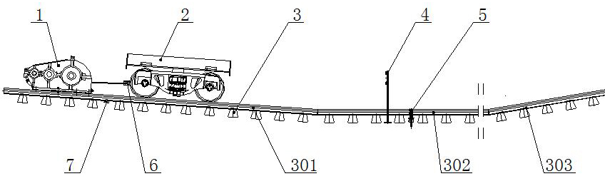
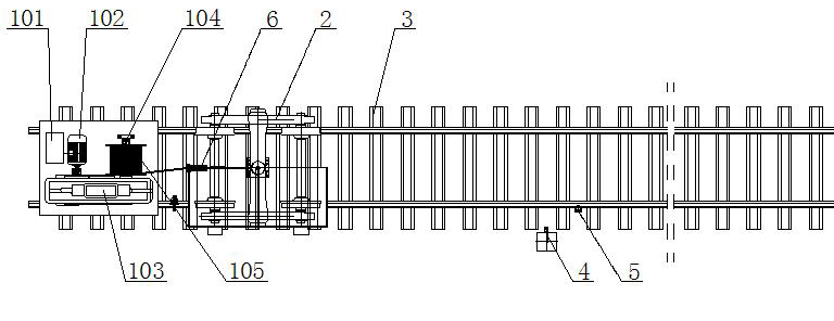
[0028] Example 1: Detection of deceleration tops of rail vehicles

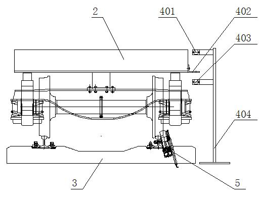
[0029] Such as Figure 1-8 As shown, the hoist 1 is set at the highest point of the acceleration ramp 301, the wheel sensor 7 is set at an appropriate position in the middle of the acceleration ramp 301, the wire rope of the hoist 1 and the test vehicle 2 are connected through the traction buffer 6, and the tested deceleration roof is installed The clamp 5 is arranged on the flat slope section 302 of the track. The tested retarder 801 is fixed to the middle of the rail of the flat slope section 302 through mounting bolts 803 and fastening nuts 804, and the retarder mounting fixture 5 is clamped on the outside of the retarder housing 802 using semicircular clips 511 and fastening bolts 512. A pressure sensor 501 and a displacement sensor 506 are provided on the retarder mounting fixture. The sensor cover 502 of the pressure sensor 501 is located under the retarder housing 802 and connected to the retarder cylinde...

Embodiment 2

[0033] Example 2: Detecting rail vehicle parking device

[0034] Such as Picture 9 As shown, when the braking capacity of the rail vehicle parking device 9 needs to be detected, the tested rail vehicle parking device 9 is installed on the flat slope section 302 of the detection line, and a set of rail vehicle parking device 9 is installed at the entrance and exit. The speed sensor 4 respectively detects the entrance speed and exit speed of the test vehicle 2 passing through the rail vehicle parking device 9, and the braking ability of the tested rail vehicle parking device 9 can be obtained through calculation.

Embodiment 3

[0035] Embodiment 3: Detection of rail vehicle stopper

[0036] Such as Picture 10 As shown, when the braking ability of the rail vehicle stopper 10 needs to be detected, the tested rail vehicle stopper 10 is installed on the flat slope section 302 of the detection line, and a set of speed sensors are installed at the entrance of the rail vehicle stopper 10 4. Detect the speed before the test vehicle 2 collides with the rail vehicle stopper 10. When the rail vehicle stopper 10 is impacted by the test vehicle 2, it will slide along the steel rail, and the braking capacity of the rail vehicle stopper 10 can be calculated by measuring the sliding distance.


PUM


Abstract

The invention provides a detection line for railway vehicle speed-reducing equipment. The detection line consists of a windlass, a traction buffer, a testing vehicle, a wheel sensor, a speed sensor, a pressure sensor, a displacement sensor, a detected equipment assembly clamp, an industrial control computer and a rail with an accelerating slope, a flat slope and a speed-reducing slope. The testing vehicle is rolled by using rail height difference, the position of the wheel sensor is changed, and the power supply of the windlass is cut off in time, so that different rolling speeds of the testing vehicle can be obtained. Technical data of the tested equipment can be acquired by various sensors, and a detection result is output through computer operation by utilizing special software. The detection line can detect and record the comprehensive performance of various types of railway vehicle speed-reducing equipment, and can replace the traditional detecting method of pushing trucks by virtue of the railway vehicle or locomotive.

Description

Technical field [0001] The invention relates to a rail vehicle deceleration equipment detection line, belonging to the technical field of performance detection of rail transit deceleration equipment. Background technique [0002] Currently widely used railway vehicle deceleration equipment, including railway vehicle retarder, railway vehicle parking device, railway vehicle stopper, railway vehicle anti-rolling device, reducer emergency protection device and so on. These equipments must undergo comprehensive performance testing of various technical indicators before leaving the factory, such as braking power, critical speed, vertical reaction force, braking ability, and so on. The traditional detection method is to use the railway track car to push the flatbed truck on the railway dedicated line. This traditional detection method has very strict requirements on the traveling speed of rail cars, especially when detecting the critical speed, the allowable error of the vehicle speed...

Claims


Application Information

Patent Timeline
IPC IPC(8): G01M13/02G01M17/08
Inventor 杨恩久赵学青赵延博
Owner SHENYANG TIEYAN TECH
Why Eureka
Try Eureka