Charged test method for current transformer and application thereof

A current transformer, live test technology, applied in instruments, measuring devices, measuring electrical variables, etc., can solve the problems of long detection period, affecting power production, billing, etc.

Active Publication Date: 2011-06-08
张建
View PDF2 Cites 66 Cited by
  • Summary
  • Abstract
  • Description
  • Claims
  • Application Information

AI Technical Summary

Problems solved by technology

[0002] The existing electromagnetic current transformer error calibration and excitation characteristic test mainly rely on periodic power failure test, not only the detection cycle is long, but also because the current transformer operates without power for a long time, once the current transformer fails or the error is out of tolerance, it will Brewing major billing or power outage losses, severe cases may also threaten other power

Method used


Image

  • Charged test method for current transformer and application thereof
  • Charged test method for current transformer and application thereof
  • Charged test method for current transformer and application thereof

Examples


Embodiment 1

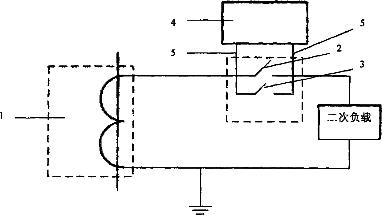
[0030] Such as figure 2 As shown, an analyzer includes the functions of live error test, live frequency response test and live excitation characteristic curve test. Such as figure 1 As shown, during the on-site live test, the analyzer 4 with the above functions is used to be connected in series with the secondary circuit of the single-phase current transformer 1 under test, and the live test of the current transformer 1 under test is carried out. The steps of the live test method are as follows:

[0031] First, keep the switch A2 and switch B3 of the secondary terminal box on the secondary side circuit of the current transformer under test 1 closed, and keep the current transformer under test 1 running with power on.

[0032] The second step is to turn on the switch A 2 of the secondary terminal box of the current transformer 1 under test, and then connect the two test line terminals 5 of the analyzer 4 to both sides of the switch of the secondary terminal box.

[0033] The...

Embodiment 2

[0045] Such as figure 1 , figure 2 As shown, the same place as in Embodiment 1 will not be repeated, and the difference is that the analyzer 4 is connected in series with the secondary circuit of the three-phase current transformer 1 under test, and the live test of the current transformer 1 under test is carried out. .

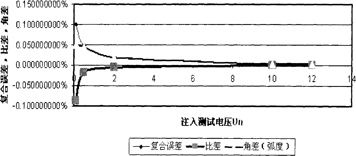
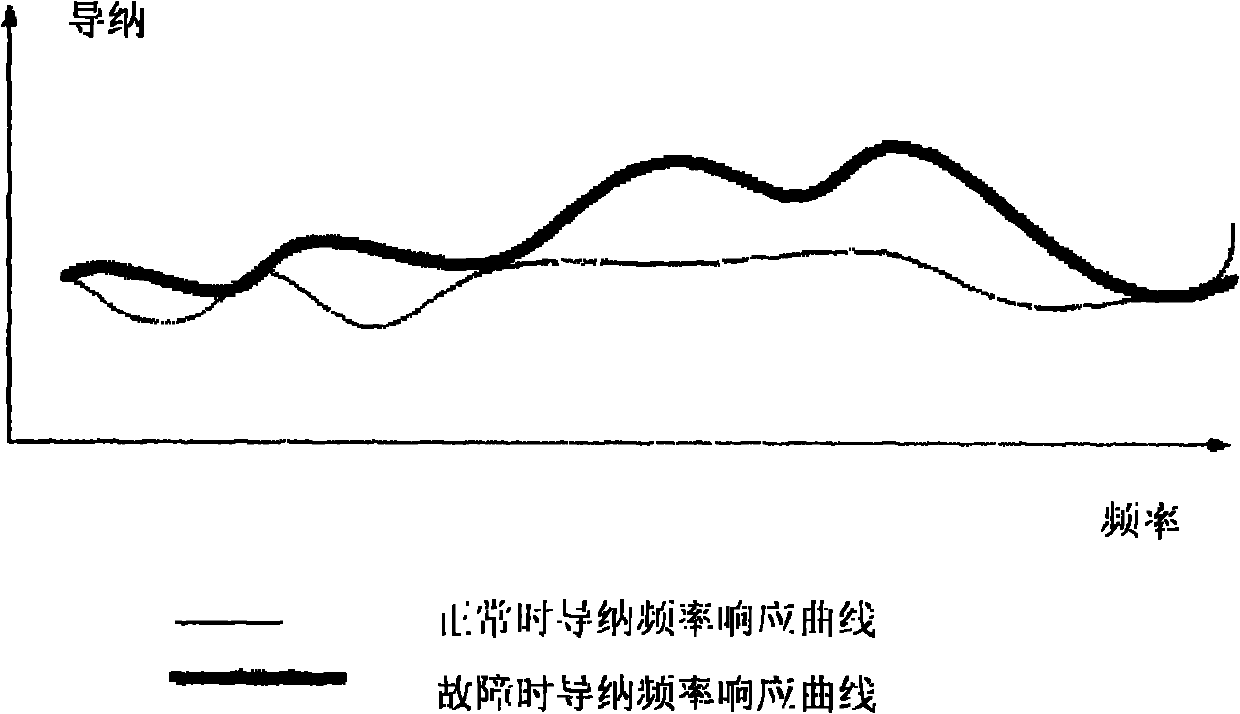
[0046] The fifth step is to select the live frequency response test: the analyzer 4 injects a different-frequency test voltage sequence different from the power frequency into the secondary circuit, and the test voltage sequence is a sine wave of a non-power frequency frequency, and the loop admittance of the corresponding frequency is tested. That is, the value of the response current divided by the injected test voltage Y = I U = g - jb , Where g is the conductance, b is the susceptance, and j is the imaginary unit. Suppose the injection test voltage U=2...

Embodiment 3

[0050] Such as figure 1 , figure 2 Shown, the place identical with embodiment 1 no longer repeats narration, and difference is:

[0051] The fifth step is to select the live excitation characteristic curve test: the analyzer 4 first tests the secondary circuit current I of the current transformer 1 under test 0 ; Then according to the secondary rated current I input in the third step s =5A, secondary rated load Z s = 2 ohms, the accurate limit value coefficient is 10, calculate the secondary rated voltage U of the measured current transformer 1 s = I s × Z s =10V, the secondary maximum voltage is 10×U s =100V, the secondary maximum impedance is 100V / 5A=20 ohms; then the resistance sequence generated by the internal resistance sequence of analyzer 4 between 0-20 ohms is connected to the secondary circuit, and the voltage sequence under the resistance condition is tested respectively u n and current sequence I n , according to the current sequence of the test I n and ...


PUM


Abstract

The invention discloses a charged test method for a current transformer and application thereof. The method comprises the following steps of: serially connecting a charged analyzer with a secondary low-voltage loop to serve as a test loop through two switches of a secondary terminal box on a secondary side loop of the current transformer under the condition of operating the charged current transformer; injecting a different-frequency test signal generated by the analyzer into the test loop through the analyzer, and realizing a charged error test and a charged frequency response test by measuring and calculating loop key parameters under an injected frequency signal; and changing a method for secondary load impedance to change excitation conditions through the analyzer, and measuring load change influence to test a charged exciting characteristic curve. Compared with the prior art, the method has the advantages that: the charged test of the current transformer can be performed without contact of primary voltage, an upward current source, a standard transformer or a load box, the safety and reliability of an uninterrupted power test are guaranteed, the equipment is high in integration, portable and light, and the method is favorable for on-site and laboratory tests and long-term online monitoring.

Description

technical field [0001] The invention relates to a detection method of a current transformer, in particular to a live test method of a current transformer and its application. Background technique [0002] Existing electromagnetic current transformer error calibration, excitation characteristic test, etc. mainly rely on periodic power failure test, not only the detection cycle is long, but also because the current transformer runs without power for a long time, once the current transformer fails or the error is out of tolerance, it will Brewing major billing or power outage losses, severe cases may also threaten other power equipment and affect power production. [0003] Although there are currently devices on the market that can be used to detect the error of electromagnetic current transformers when they are live, operators need to be exposed to high voltage (up to 1000kV) once, and they need to carry a large number of equipment such as current boosting sources, standard tr...

Claims


Application Information

Patent Timeline
IPC IPC(8): G01R35/02
Inventor 张建
Owner 张建
Why Eureka
Try Eureka