Portable grid-connected current converter test device

A test device and converter technology, which is applied in the field of converter testing, can solve problems such as inability to fully test converters, and achieve the effect of being convenient for on-site testing, easy to carry, and small in size

Active Publication Date: 2017-11-24
SHENZHEN AUTO ELECTRIC POWER PLANT
View PDF9 Cites 1 Cited by
  • Summary
  • Abstract
  • Description
  • Claims
  • Application Information

AI Technical Summary

Problems solved by technology

[0007] The purpose of the present invention is to solve the problem that the power signal provided by the grid-connected converter test system in the prior art only tests the switching devices of the converter and cannot fully test the converter

Method used


Image

  • Portable grid-connected current converter test device
  • Portable grid-connected current converter test device
  • Portable grid-connected current converter test device

Examples


Embodiment 1

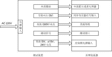
[0026] In order to solve the problem that the power signal provided by the grid-connected converter test system in the prior art is only tested for the converter switching device, and the converter cannot be tested comprehensively, the present invention provides a method such as figure 1 The portable grid-connected converter test device shown includes a power input terminal, a current excitation output module, an AC voltage output module, a first DC voltage output module, and a drive signal output module;

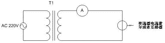
[0027] Such as figure 2 The current excitation output module shown includes a step-down transformer T1 and a low-resistance wire short-circuited with the step-down transformer T1. The primary side of the step-down transformer T1 is electrically connected to the power input terminal, and the secondary side of the step-down transformer T1 Short-circuit connection by connecting low-resistance wires to form a closed loop with the current hall of the converter or current transformer...

Embodiment 2

[0036] Such as figure 2 As shown, the AC 220V voltage is connected to the primary side of the step-down transformer T1, and the secondary side of T1 (output voltage 1V) is short-circuited by a long low-resistance wire, and the long wire is formed by the current hall of the converter or the current transformer Closed loop; grid-connected converter needs AC current sampling function. Taking static reactive power generator as an example, on the one hand, it needs to sample the output current for closed-loop control, on the other hand, it needs to sample the load current to compensate the load current. Reactive current in. In order to test the current sampling function, the test device needs to provide high current excitation. The test device has a built-in low output voltage (1V) isolation transformer. The short-circuit current is generated by shorting the secondary side of the transformer to provide signal excitation for current sampling. The detection of the current sampling ac...


PUM


Abstract

The invention belongs to the technical field of the current converter test, and particularly relates to a portable grid-connected current converter test device comprising a power supply input end, a current excitation output module, an AC voltage output module, a first DC voltage output module and a drive signal output module. The current converter test is enabled to be more comprehensive, the signal of the switching device of the current converter for the test can be provided, and the signal of voltage and current of the current converter for simulation sampling and the test can also be provided without independently using a switching power supply, an AC current generation device, an AC voltage generation device, a DC power supply or other equipment for simulation sampling of the current converter and the test of the power device, and the integrated module design is adopted and thus the size is small, carrying is convenient and field testing can be realized.

Description

Technical field [0001] The invention belongs to the technical field of converter testing, and specifically relates to a grid-connected converter suitable for static reactive power generators (SVG), active power filters (APF), photovoltaic inverters, power converters (PCS), etc. The factory test and field test of the inverter can also be used as a portable grid-connected converter test device for inverter test. Background technique [0002] A converter is an electrical device that changes the voltage, frequency, number of phases, and other power or characteristics of the power supply system. Including rectifier (AC to DC <AC / DC> ), inverter (DC to AC <DC / AC> ), AC converter (AC inverter <AC / AC> ) And DC converter (DC chopper <DC Chopper> ) [0003] With the development of power electronics technology, grid-connected converters are becoming more and more widely used in power systems. Because the main circuit and control system of grid-connected converters are...

Claims


Application Information

Patent Timeline
Patent Type & Authority Applications(China)
IPC IPC(8): G01R31/40
CPCG01R31/40
Inventor 李计亮许崇福袁国权
Owner SHENZHEN AUTO ELECTRIC POWER PLANT
Why Eureka
Try Eureka