Wafer spray cleaning method

A technology of wafers and nozzles, which is applied in the field of wafer spray cleaning and wafer cleaning, and can solve the problems of reduced cleaning efficiency and affecting output rate, etc.

Active Publication Date: 2011-06-15
SEMICON MFG INT (SHANGHAI) CORP +1
View PDF0 Cites 3 Cited by
  • Summary
  • Abstract
  • Description
  • Claims
  • Application Information

AI Technical Summary

Problems solved by technology

The cleaning efficiency is greatly reduced, which will also affect the output rate

Method used


Image

  • Wafer spray cleaning method
  • Wafer spray cleaning method
  • Wafer spray cleaning method

Examples


Embodiment Construction

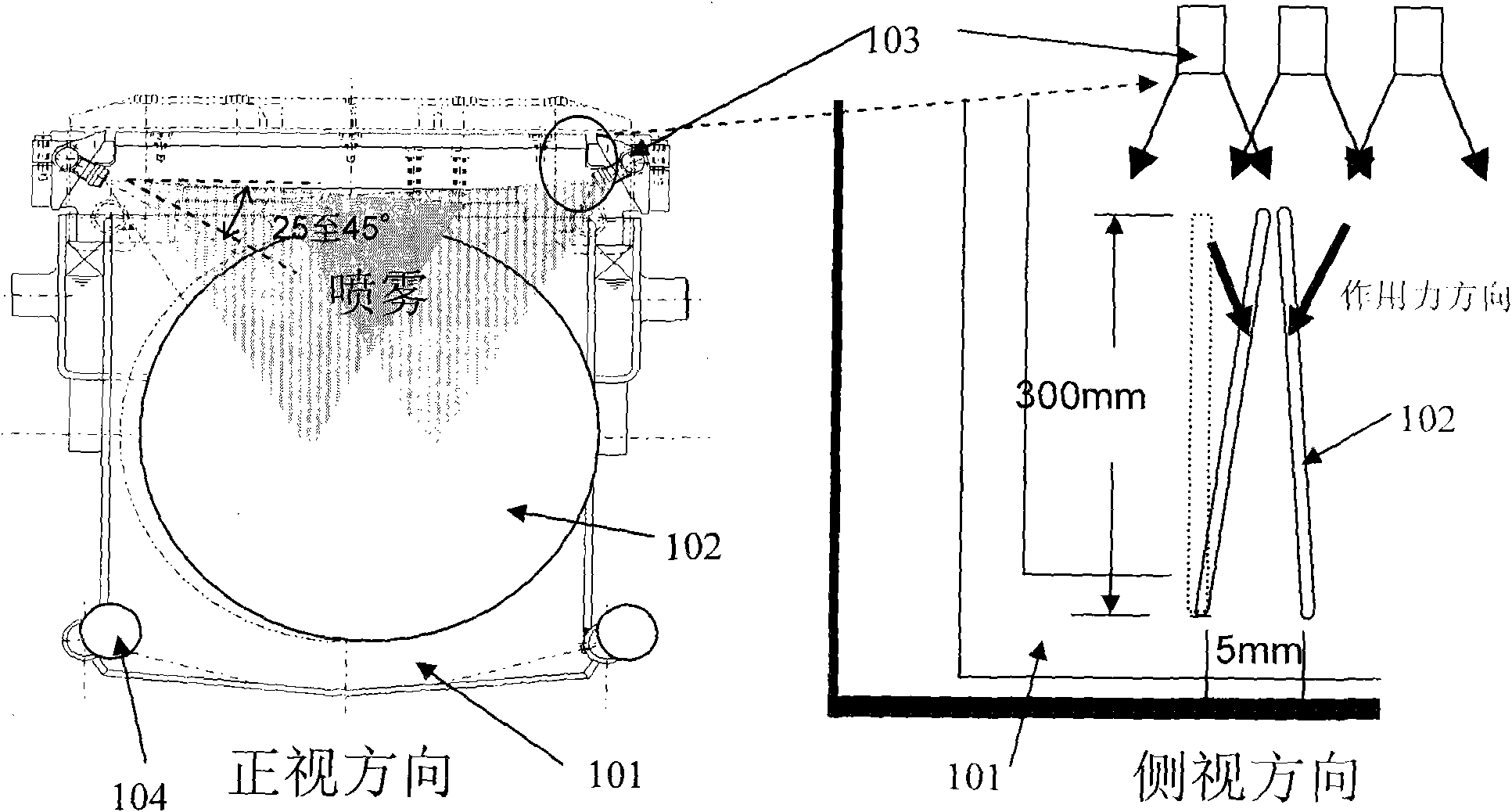
[0024] The object of the present invention is to keep the distance between the wafers at 5 mm, so that the swing range of the wafers during the spray cleaning process is small enough so that adjacent wafers do not contact. According to the previous analysis, the liquid droplets ejected from the nozzle exert a force on the wafer, and the moment of this force relative to the fixed point of the wafer is the root cause of the swing of the product circle. It is therefore the object of the present invention to actually reduce this moment.

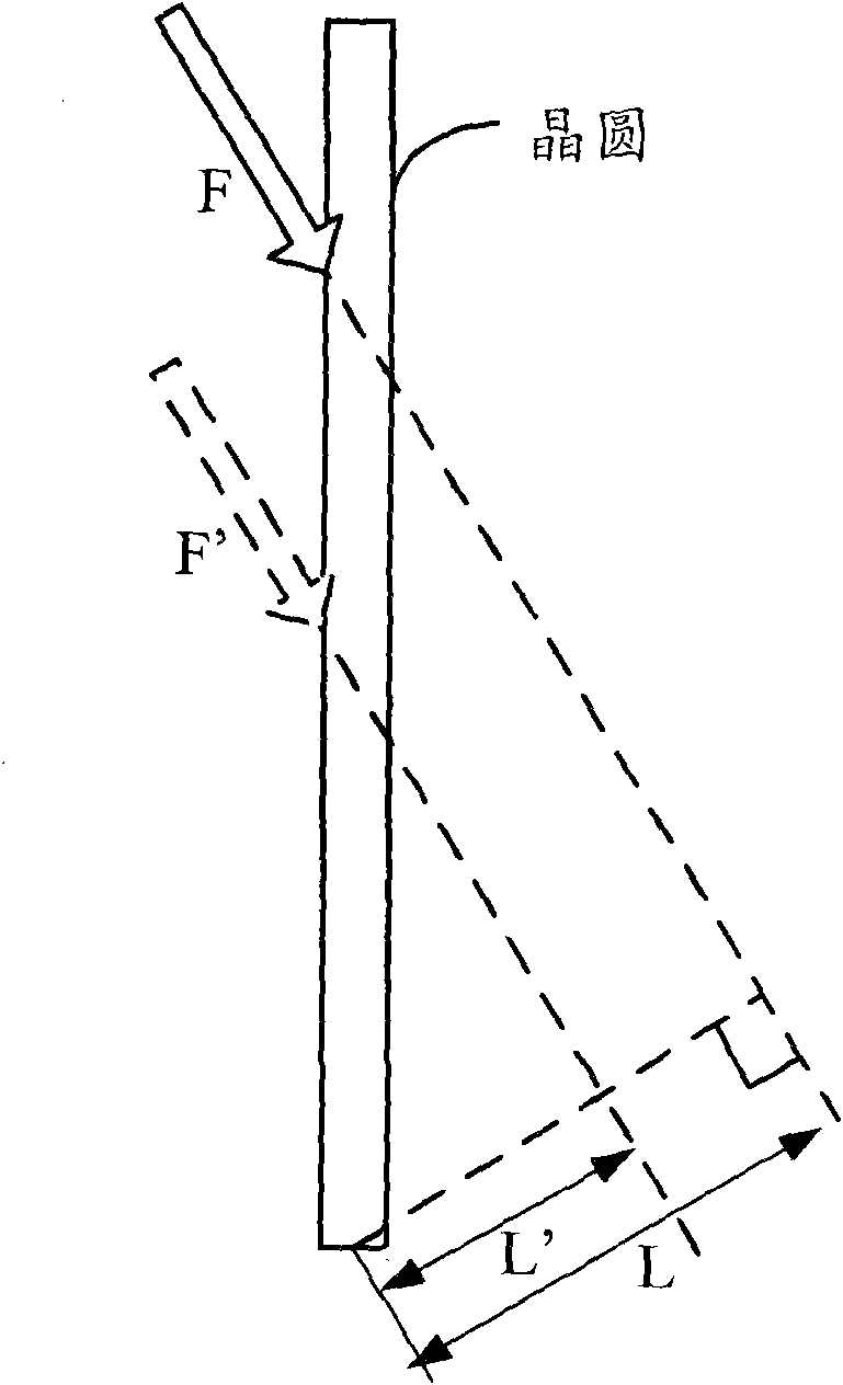
[0025] According to the physical definition of torque: torque M=L×F, where F is the force, L is the distance from the point of action of F to the axis of rotation, figure 2 It is a schematic diagram of the wafer being subjected to the droplet force during the spray cleaning process. From figure 2 It can be seen intuitively that to reduce the moment M, the options available include:

[0026] (1), reduce the size of the force F. The force F i...


PUM


Abstract

The invention discloses a wafer spray cleaning method, which is to fix a plurality of wafers to be cleaned on a chuck in turn and fix the chuck on a transmission device of a spray cleaning platform. The method comprises the following steps: opening a quick water discharge tank to discharge the residual liquid in the quick water discharge tank completely; starting the transmission device and a timer set in a preset time period at the same time; when the timer runs the preset time period, opening a spray nozzle positioned above the wafers, so that spray cleaning chemical liquid drops are sprayed from the spray nozzle onto the surface of the wafers along an oblique direct when the transmission device drives the chuck and the wafers fixed on the chuck to move up and down; and after cleaning is finished, closing the spray nozzle and the quick water discharge tank and stopping the transmission device. According to the technical scheme of the invention, the mutual contact phenomena between adjacent wafers are reduced, and 50 or more wafers can be cleaned in one batch while in the prior art only 25 wafers can be cleaned in one batch.

Description

technical field [0001] The invention relates to the technical field of semiconductor integrated circuit manufacturing, in particular to a wafer cleaning technology, in particular to a wafer spray cleaning method. Background technique [0002] As critical dimensions on wafers continue to shrink, wafer surfaces must be clean before undergoing processing. Although integrated circuit processing workshops have extremely strict requirements for cleanliness, contamination of wafers is inevitable. Once the wafer surface is contaminated, the contamination must be removed by cleaning. The most commonly used cleaning method is wet chemical cleaning, referred to as wet cleaning. [0003] A common type of wet cleaning is spray cleaning. In the spray cleaning station, the wet cleaning chemical is sprayed in the form of small mist droplets to the surface of the wafer fixed on the chuck, and then the wet cleaning chemical flows to the bottom of the chuck and passes through the quick drai...

Claims


Application Information

Patent Timeline
Patent Type & Authority Applications(China)
IPC IPC(8): B08B3/02B08B3/08
Inventor 谢志勇
Owner SEMICON MFG INT (SHANGHAI) CORP
Why Eureka
Try Eureka