Ball forming mechanism of steel ball rolling mill with quickly assembled ball rolling rollers

A fast, ball-rolling technology, applied in the direction of mechanical equipment, bearing components, shafts and bearings, etc., can solve problems such as inability to disassemble, troublesome loading and unloading, fastening nuts rusted together, etc., and achieve the effect of avoiding chattering

Active Publication Date: 2012-10-10
CHANGSHU FEIFAN METALWORK
View PDF2 Cites 36 Cited by
  • Summary
  • Abstract
  • Description
  • Claims
  • Application Information

AI Technical Summary

Problems solved by technology

[0003] However, the technical solution announced by the aforementioned CN101934334A still has the following shortcomings: one is that the mutual assembly or disassembly of the upper beam (a pair) and the bracket column (a pair) constituting the bracket is relatively troublesome, because the upper beam and the bracket column The connection is realized through the fastening screw hinged on the top of the support column and by means of the fastening nut. Therefore, when the ball roller is to be replaced, the upper beam must be separated from the support column first, so that the lifting device such as a crane It takes a long time to lift the ball forming roller from the support and remove the fastening nut previously located on the fastening screw, especially once the thread on the fastening screw is damaged (such as broken teeth), the fastening nut cannot be used. Unloading from the fastening screw, unless the fastening screw is sawed off, and the fastening nut is easily rusted together with the fastening screw, which will cause trouble for disassembly; the second is the pull rod and adjusting screw of the ball forming roller parallel distance adjustment device The connection with the connecting plate is unreasonable, especially because the adjusting screw is directly connected with the connecting plate, which will cause trouble for loading and unloading the ball roller, because if the ball forming roller is to be hoisted from the bracket, the adjusting screw (a pair) and the pull rod (located between a pair of adjusting screws), but to remove the adjusting screw and the pull rod, the connecting plate must be removed first, which also takes a long time; the third is a total of four on a pair of upper beams. The connection between the compression screw and the top of the four shaft seats of a pair of ball forming rollers is unreasonable. For example, it is necessary to preset the shaft seat connection seat on the surface (top surface) of each shaft seat facing the compression screw, which is suitable for this. Therefore, a pin hole is provided at the end where each compression screw is connected to the shaft seat connection seat, and the pin shaft will hinge the compression screw rod and the shaft seat connection seat. This structure is not good for manufacturing, installation or disassembly, and still requires It takes a long time; the fourth is that the connection between the four compression screws on the aforementioned pair of upper beams and the shaft seat connecting seats at the top of the four shaft seats is a pivotal connection, so there is a gap between the two, which is not conducive to Alignment of the top of the shaft seat

Method used


Image

  • Ball forming mechanism of steel ball rolling mill with quickly assembled ball rolling rollers
  • Ball forming mechanism of steel ball rolling mill with quickly assembled ball rolling rollers

Examples


Embodiment Construction

[0019] In order to enable the examiners of the patent office, especially the public, to understand the technical essence and beneficial effects of the present invention more clearly, the applicant will describe in detail below in conjunction with the accompanying drawings in the form of embodiments, but none of the descriptions of the embodiments is a description of the present invention. Restriction of the inventive solution, any equivalent transformation made according to the concept of the present invention which is only in form but not in substance shall be regarded as the scope of the technical solution of the present invention.

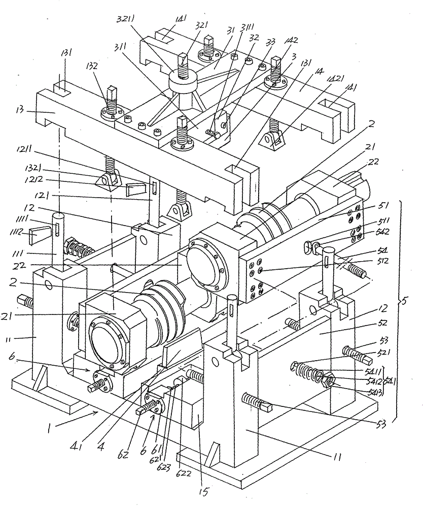
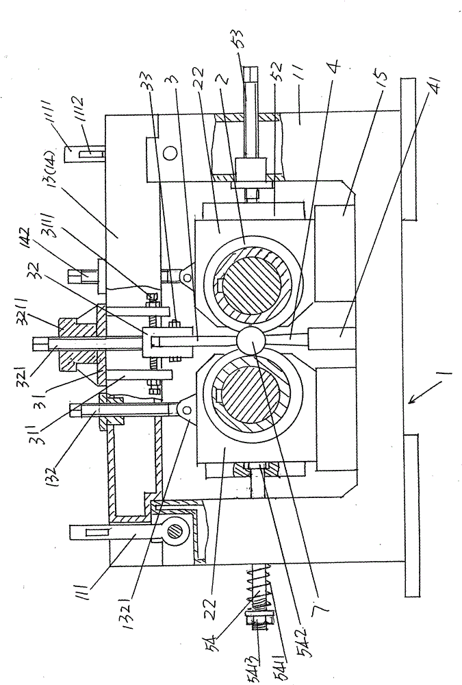
[0020] please see figure 1 and figure 2 , the given support 1 is made up of a pair of first support columns 11, a pair of second support columns 12, a first upper beam 13 and a second upper beam 14, and the bottom of a pair of first support columns 11 is formed by the bottom beam Connection, the bottom of the same pair of second support column...


PUM


Abstract

The invention discloses a ball forming mechanism of a steel ball rolling mill with quickly assembled ball rolling rollers, and belongs to a steel ball processing machine. The ball forming mechanism comprises a bracket, a pair of ball forming rollers, upper and lower ball stop plates and a pair of ball forming roller parallel distance adjusting device. The ball forming mechanism is characterized in that: two ends of a first upper cross beam are provided with first locking rod grooves, the upper ends of a pair of first bracket upright posts are hinged with first locking rods, and one end of thefirst locking rod is provided with a first mortise; two ends of a second upper cross beam are provided with second locking rod grooves, the upper ends of a pair of second bracket upright posts are hinged with second locking rods, and one end of the second locking rod is provided with a second mortise; a connecting plate is provided with a pull rod head hole, a pull rod head is formed at one end of a pull rod, and the end faces of a pair of adjusting screws are propped against the surface of a connecting block; and the first upper cross beam is provided with a first compaction screw, the lowerend of the screw is hinged with a first pressure pin, the second upper cross beam is provided with a second compaction screw, and the lower end of the screw is hinged with a second pressure pin. The ball forming mechanism is convenient and quick to assemble or disassemble, and can ensure the parallel distance of a pair of ball forming rollers and prevent a shaft seat from carrying the ball forming rollers to cause shake and jump.

Description

technical field [0001] The invention belongs to the technical field of steel ball processing machinery, and in particular relates to a ball forming mechanism of a steel ball rolling machine whose ball rolling rollers can be quickly loaded and unloaded, and is used for rolling metal bars heated by a heating furnace into spheres. Background technique [0002] As described in the ball forming mechanism (the applicant's application) of the steel ball rolling machine announced by the invention patent application publication number CN101934334A: the roundness of the steel ball sphere is guaranteed by the parallelism of a pair of ball forming rollers. When a pair of ball forming rollers is in working condition, on the one hand, the bar is rolled into a ball (sphere), but at the same time, the sphere also produces a huge reaction force on the ball forming rollers, and the reaction force imperceptibly makes the gap between the pair of ball forming rollers The parallelism of the rolle...

Claims


Application Information

Patent Timeline
Patent Type & Authority Patents(China)
IPC IPC(8): B21H1/14
Inventor 陈刚
Owner CHANGSHU FEIFAN METALWORK
Why Eureka
Try Eureka