
Processing technique for heavy crankshaft and shaft part milling frame stations and technique equipment

A technology of shaft parts and processing technology, applied in the field of heavy crankshaft and shaft parts rack processing, can solve the problems of poor rack surface quality, high cost, small load-bearing tonnage of machine tools, etc., to improve product quality and competitiveness, The effect of simplifying the machining process and improving the efficiency

Active Publication Date: 2011-06-15
TONGYU HEAVY IND
View PDF4 Cites 10 Cited by
  • Summary
  • Abstract
  • Description
  • Claims
  • Application Information

AI Technical Summary

Problems solved by technology

[0004] In order to overcome the deficiencies of the existing technology, the present invention provides a milling stand processing technology and technological equipment for heavy-duty crankshafts and shaft parts to solve the problem of eccentricity of the workpiece, large tonnage, small load-bearing tonnage of the machine tool, and poor surface quality of the stand during the processing. High cost and low efficiency

Method used


Image

  • Processing technique for heavy crankshaft and shaft part milling frame stations and technique equipment
  • Processing technique for heavy crankshaft and shaft part milling frame stations and technique equipment
  • Processing technique for heavy crankshaft and shaft part milling frame stations and technique equipment

Examples


Embodiment Construction

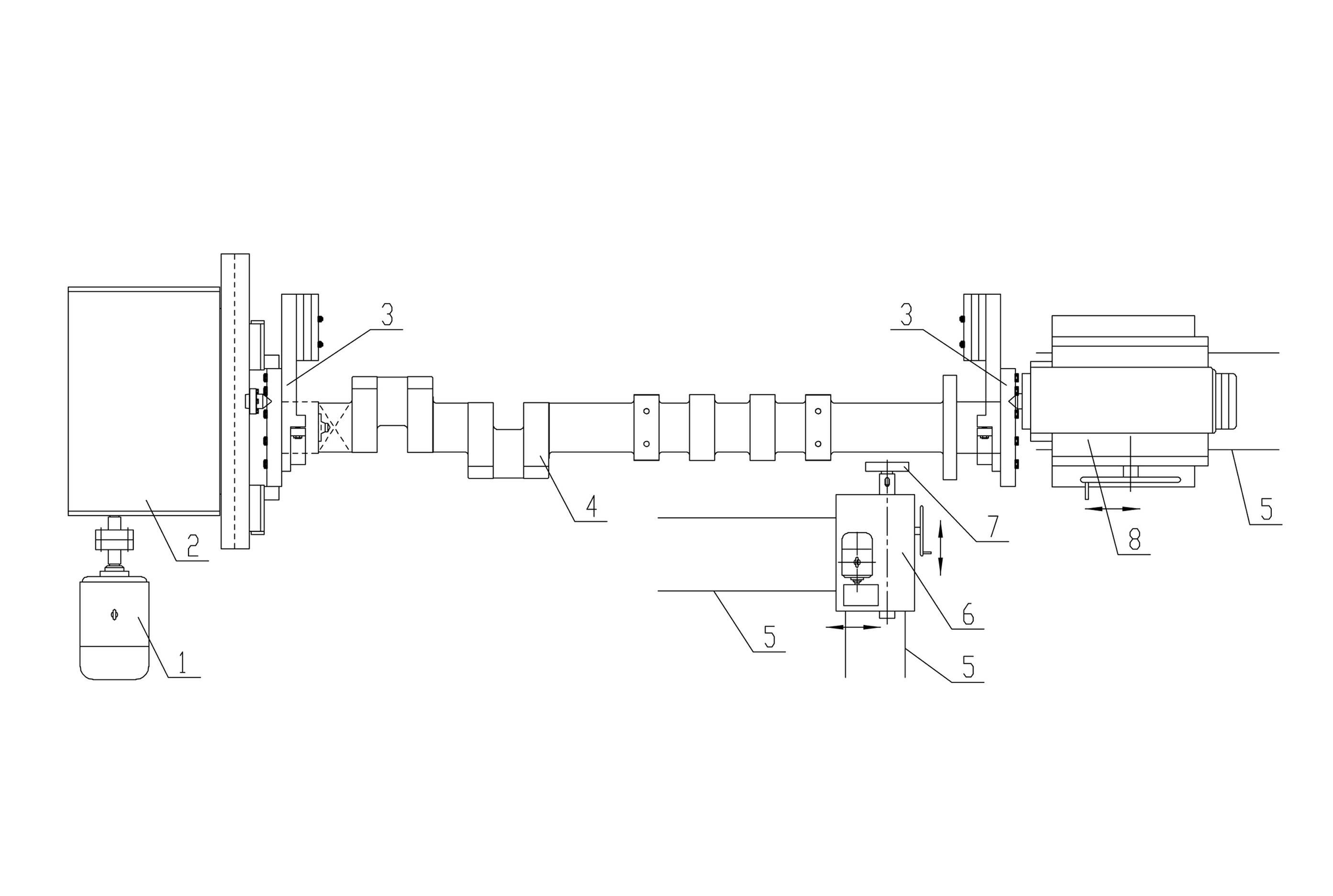
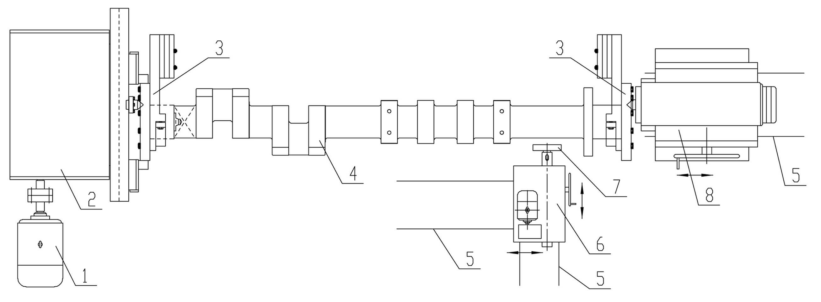
[0026] Such as Figure 1-2 As shown: the technical solution is to add a counterweight mechanism, change the traditional turning to milling, and break away from the support of the center frame and the processing of large-tonnage rough turning machine tools, forming a new processing technology. The process equipment is mainly composed of a DC motor 1, a rotating mechanism 2, a counterweight mechanism 3, a workpiece 4, a slideway 5, a boring and milling power head 6, a milling cutter disc 7, and a clamping mechanism 8.

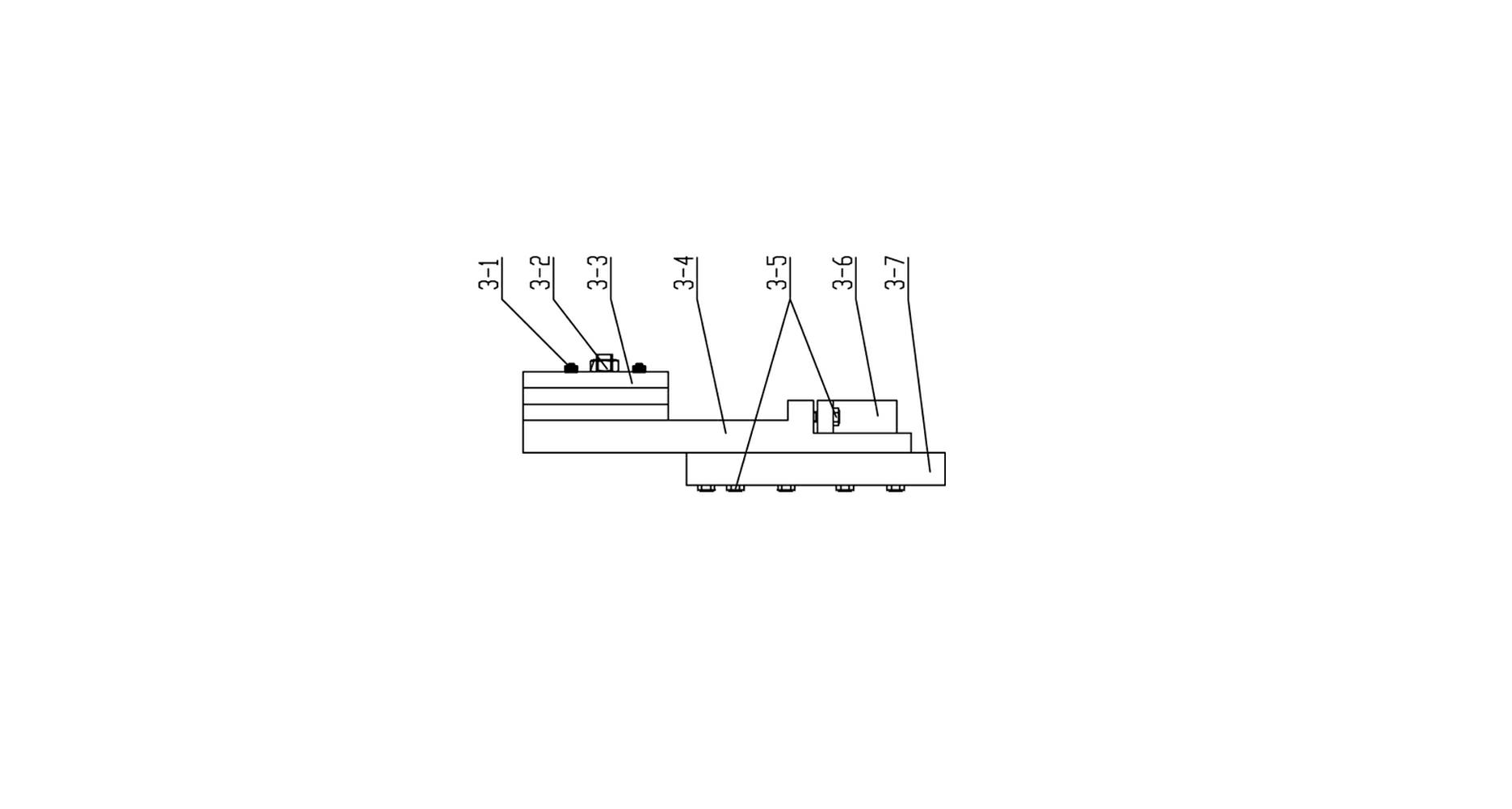
[0027] The counterweight mechanism consists of stud bolts 3-1, T-shaped bolts 3-2, counterweight blocks 3-3, counterweight carcass 3-4, closing bolts 3-5, gland 3-6, top plate 3- 7 composition. The stud bolt 3-1 and the T-bolt 3-2 fix the counterweight 3-3 on the counterweight carcass 3-4, and the gland 3-6 and the counterweight carcass 3-4 are tightened to secure the workpiece 4. The shaft ends are clamped, and the counterweight carcass 3-4 is connected with t...


PUM


Abstract

The invention discloses a processing technique for heavy crankshaft and shaft part milling frame stations and technique equipment, and belongs to the technical field of machinery manufacture. The processing technique equipment is separated from the supporting of a central frame and the processing of a large tonnage rough turning machine tool, a worm gear and a transmission gear are arranged in a rotating mechanism of the equipment, a motor drives the transmission gear in the rotating mechanism, and an apex is arranged on the inner sides of the rotating mechanism and a jacking mechanism respectively; a workpiece is arranged between the two apexes; a counterweight mechanism consists of a stud bolt, a T-shaped bolt, a counterweight block, a counterweight carcass, a closing bolt, a gland and a top tray; the counterweight block is fixed on the counterweight carcass through the stud bolt and the T-shaped bolt; the counterweight carcass is connected with the top tray through the closing bolt; and the left side of the workpiece is provided with a boring and milling power head, and the lower side and the outer side of the workpiece are provided with slide ways. A finished workpiece is obtained by adopting the tooling equipment and the processes of determining the position of a central hole, drilling the central hole, fixing the workpiece, determining the longitudinal position of the boring and milling power head, determining the transverse position of the boring and milling power head, processing the rest frame stations, checking and warehousing.

Description

technical field [0001] The invention belongs to the technical field of mechanical manufacturing, and relates to the processing technology of heavy-duty crankshafts and shaft parts. Background technique [0002] At present, the machining process of heavy or long crankshafts and shaft parts consists of the following process steps: the first step: draw the central axis of the workpiece, and draw the position of the center hole on both ends; the second step: drill on both ends Countersinking the center hole; the third step: positioning the two tops on the lathe, the chuck drives the workpiece to rotate to make the main movement, and the corresponding stand position is turned out by the car; the fourth step: polishing the stand position. [0003] The disadvantages of traditional technology and technology equipment are: (1) The equipment used is a special crankshaft lathe for processing, and the investment in special machine tools is relatively large; (2) Heavy or long shaft blank...

Claims


Application Information

Patent Timeline
IPC IPC(8): B23C3/00
Inventor 司兴奎陈练练刘玉海黄克垠刘宝刚
Owner TONGYU HEAVY IND
Learn More