Wind machine blade airfoil profile capable of controlling flow stalling through standing vortex

A wind turbine blade, flow control technology, applied to the airfoil of the wind turbine blade. In this field, it can solve the problems of high angle of attack, high lift and flow stall, and achieve the effect of expanding the working range of angle of attack, reducing the risk of structural damage, and reducing unsteady loads

Inactive Publication Date: 2011-06-15
NORTHWESTERN POLYTECHNICAL UNIV
View PDF6 Cites 16 Cited by
  • Summary
  • Abstract
  • Description
  • Claims
  • Application Information

AI Technical Summary

Problems solved by technology

[0005] In order to overcome the shortcomings in the existing large-thickness wind turbine airfoil design technology that cannot take into account the high angle of attack, high lift condition and flow stall phenomenon, the present invention proposes a wind turbine blade airfoil that controls flow stall through vortex

Method used


Image

  • Wind machine blade airfoil profile capable of controlling flow stalling through standing vortex
  • Wind machine blade airfoil profile capable of controlling flow stalling through standing vortex
  • Wind machine blade airfoil profile capable of controlling flow stalling through standing vortex

Examples


Embodiment 1

[0024] In this implementation, the purpose of this embodiment is realized by modifying the upper surface of the basic airfoil and installing Gurney flaps at the trailing edge point of the basic airfoil.

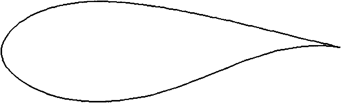
[0025] as attached image 3 As shown, this embodiment selects the FFA-W3-301 fan airfoil as the basic airfoil. The chord length of the basic airfoil is 983.5mm.

[0026] as attached Figure 4 As shown, on the upper airfoil of the basic airfoil, the airfoil between the modification starting point 1 and the airfoil trailing edge point 6 is modified. Place the upper surface of the base airfoil in the xoy plane and make the chord of the airfoil coincide with the x-axis.

[0027] The leading edge point of the airfoil is located at the coordinate origin O, and the trailing edge point of the airfoil is located on the positive semi-axis of the x-axis.

[0028] When trimming, the position of 30% chord length from the upper airfoil to the leading edge point of the airfoil is taken ...

Embodiment 2

[0038] This implementation is to make a fan airfoil for wind power generation.

[0039] In this implementation, the purpose of this embodiment is realized by modifying the upper surface of the basic airfoil and installing Gurney flaps at the trailing edge point of the basic airfoil.

[0040] as attached image 3 As shown, this embodiment selects the FFA-W3-301 fan airfoil as the basic airfoil. The chord length of the basic airfoil is 983.5mm.

[0041] as attached Figure 5 As shown, on the upper airfoil of the basic airfoil, the airfoil between the modification starting point 1 and the airfoil trailing edge point 6 is modified. The upper surface of the basic airfoil is placed in the xoy plane, so that the leading edge point of the airfoil is located at the coordinate origin O, and the trailing edge point of the airfoil is located on the positive semi-axis of the x-axis.

[0042] When trimming, take the position of 35% chord length from the upper airfoil of the airfoil to the...

Embodiment 3

[0052] This implementation is to make a fan airfoil for wind power generation.

[0053] In this implementation, the purpose of this embodiment is realized by modifying the upper surface of the basic airfoil and installing Gurney flaps at the trailing edge point of the basic airfoil.

[0054] as attached image 3 As shown, in this embodiment, the NACA-63-430-V fan airfoil is selected as the basic airfoil. The chord length of the basic airfoil is 1000mm.

[0055] as attached Figure 5 As shown, on the upper airfoil of the basic airfoil, the airfoil between the modification starting point 1 and the airfoil trailing edge point 6 is modified. The upper surface of the basic airfoil is placed in the xoy plane, so that the leading edge point of the airfoil is located at the coordinate origin O, and the trailing edge point of the airfoil is located on the positive semi-axis of the x-axis.

[0056] When trimming, the position of 40% of the chord length from the upper airfoil to the ...


PUM

PropertyMeasurementUnit
Chord lengthaaaaaaaaaa

Abstract

The invention relates to a wind machine blade airfoil profile capable of controlling flow stalling through standing vortex. An airfoil profile between a shaping starting point and an airfoil profile trailing edge point is modified, thus a concave pit is formed; the shaping starting point and the airfoil profile trailing edge point are connected through a straight line, a concave pit starting point and a concave ending point are connected by virtue of a 1 / 4 circular arc, and the concave ending point, a first transition point, a second transition point and the airfoil profile trailing edge point are connected through a B spline; and the airfoil profile trailing edge is provided with a Gurney wing flap. According to the invention, the amplitude of the thickness reduction of the upper surface is slowed down to delay the separation of the flow field of the upper airfoil, vortex with a fixed position is formed by the air flow at the concave pit of the upper surface, under the action of the vortex, the separation of the upper surface of the airfoil can be controlled effectively, the irregular falling of separated vortex is avoided, and vortex lifting force is formed at the upper surface of the airfoil, and the stalling of the airfoil is slowed down, so that the stalling incidence of the airfoil is improved.

Description

technical field [0001] The invention relates to the field of fan blade airfoils, in particular to a fan blade airfoil. Background technique [0002] As the worldwide energy crisis continues to emerge, the utilization of wind energy has been paid more and more attention by countries all over the world. According to relevant literature statistics, wind energy resources are very abundant on the earth, and the global wind energy reserves are about 2.74×10 9 MW, the economically exploitable wind energy can still reach 2×10 7 MW is 10 times larger than the total amount of hydropower that can be developed and utilized. [0003] In the development of wind turbines in recent years, the attached figure 1 A trend graph of the maximum size of wind turbines over the past 25 years. Obviously, as the size of fan blades becomes larger, the efficiency of wind energy utilization is higher. However, in order to ensure that the blades have sufficient structural strength, the relative thickn...

Claims


Application Information

Patent Timeline
IPC IPC(8): F03D11/00
CPCY02E10/722Y02E10/72
Inventor 叶正寅叶坤武洁
Owner NORTHWESTERN POLYTECHNICAL UNIV
Why Eureka
Try Eureka