Humidifier

A technology of humidifiers and water stoppers, applied in ultrasonic humidifiers, air humidification systems, heating methods, etc., can solve the problems of complex manufacturing of water tanks, easy cracking, water leakage, and diffuse water mist, and achieve the quality of avoiding imprecise ultrasonic welding problems, avoid ultrasonic bonding wire cracking, and the effect of not being easily broken

Inactive Publication Date: 2013-02-13
贺发民
View PDF0 Cites 2 Cited by
  • Summary
  • Abstract
  • Description
  • Claims
  • Application Information

AI Technical Summary

Problems solved by technology

[0009] The first technical problem to be solved by the present invention is to provide a method to prevent water mist from leaking without water mist leakage at the joint between the water tank and the water tank in view of the defect of water mist leakage between the water tank and the water tank of the ultrasonic water mist generating mechanism in the prior art. Humidifier with simple structure and good leakage prevention effect
[0010] The technical problem to be solved by the present invention is to provide a humidifier with no splicing of the water tank, simple manufacture, independent water tank and water mist distribution pipe, and not easy to break and leak, aiming at the defects of complicated water tank manufacturing and easy cracking and water leakage in the prior art
[0011] The further technical problem to be solved by the present invention is to address the defects in the prior art that when the water tank is lifted to add water, the oscillating plate continues to work, causing water mist to diffuse and agitated water columns or splashes to splash out of the humidifier, and when there is no water tank or the water tank is not put in place , the product is still working when there is a lack of water due to misoperation, which will cause premature damage to the product

Method used


Image

  • Humidifier
  • Humidifier
  • Humidifier

Examples


Embodiment Construction

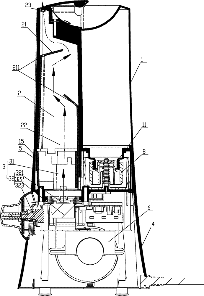
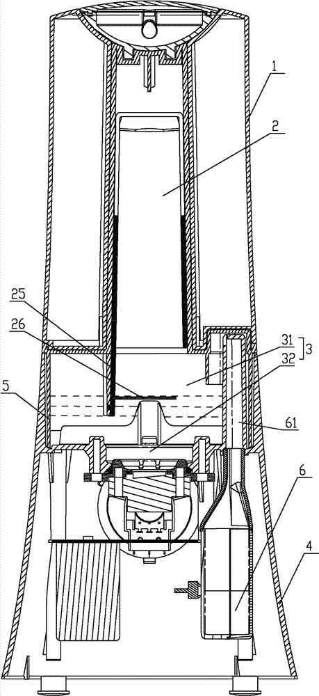
[0050] Such as figure 1 , 2 As shown, a humidifier includes a base 4 and a water tank 1 arranged above the base 4. The upper part of the base 4 is provided with an ultrasonic water mist generating mechanism 3, and the lower part is provided with an air supply mechanism 6 for increasing the diffusion speed of the water mist. And the control mechanism (not shown in the figure) that is used to control the operation of the humidifier, the water mist distribution pipe 2 is also arranged above the base 4 . Wherein the effect of base 4 is to be used for supporting water tank 1 and as the shell that encloses ultrasonic water mist generating mechanism 3, blower mechanism 6 and control mechanism.

[0051] Such as figure 1 , 2 As shown, the ultrasonic water mist generating mechanism 3 includes a water tank 31 arranged on the upper part of the base 4. The water tank 31 can be a tank body that is independently provided and set on the upper part of the base 4, or can directly use the wat...


PUM


Abstract

The invention relates to a humidifier, which comprises a base, a water tank and a water fog diffusing tube. An ultrasonic water fog generating mechanism, an air supply mechanism and a control mechanism are arranged in the base; the ultrasonic water fog generating mechanism comprises a water trough arranged on the upper part of the base; an ultrasonic oscillator is arranged at the bottom of the water tank; a leakage protective hood for enclosing the space above the ultrasonic oscillator is arranged above the ultrasonic oscillator; the leakage protective hood is peripherally inserted into the water trough and is immerged in the water; the water fog diffusing tube is hermetically connected with the leakage protective hood and is communicated with the space in the leakage protective hood; and a fog baffling plate is arranged in the water fog diffusing tube. The invention provides a humidifier which has no water fog leakage at the matching position of the water tank and the water trough, and has simple structure and good leakage protective effect.

Description

technical field [0001] The invention belongs to the technical field of electric appliances and relates to a humidifier. Background technique [0002] Relevant studies have shown that in the past 30 years, with the increase of global temperature year by year, the air humidity has been decreasing year by year. The incidence of diseases such as influenza, bronchial asthma, allergic dermatitis, and emphysema has increased by more than 30% compared with 30 years ago; People in a sub-healthy state have weaker body resistance than healthy people and are vulnerable to viruses and bacteria, and low humidity environments are conducive to germs The reproduction and spread of germs are even more rampant. But when the air humidity reaches 55%, it is difficult for germs to spread, so the air humidity that is beneficial to human health should be kept between 45% and 55%. However, there are few families in modern cities that meet this standard. In response to the above situation, people ...

Claims


Application Information

Patent Timeline
Patent Type & Authority Patents(China)
IPC IPC(8): F24F6/12F24F11/02F24F13/24F16J15/00F16J15/14
CPCY02B30/80Y02B30/70
Inventor 贺发民
Owner 贺发民
Why Eureka
Try Eureka