
Far-field target marker and application of optical fiber panel

An optical fiber panel, marker technology, applied in the direction of instruments, light sources, electric light sources, etc., can solve the problem of not eliminating sunlight effects, high and low temperature resistance, radiation resistance, unable to guarantee radiation beam single peak, smooth and symmetrical, unable to Adapt to the problem of action distance, etc., to achieve the effect of light weight, low power consumption and small size

Inactive Publication Date: 2011-06-15
李金宗
View PDF0 Cites 3 Cited by
  • Summary
  • Abstract
  • Description
  • Claims
  • Application Information

AI Technical Summary

Problems solved by technology

[0005] 2. Since the far-field target marker uses LEDs / IREDs light source, its radiation power is limited. Even if its light source uses 20 to 40 LEDs / IREDs, the total radiation power is only a few hundred mW, which cannot be compared with the intensity of sunlight
[0006] 3. Since the actual radiation beam of the far-field target marker is synthesized by the radiation beams of all light-emitting devices of its light source, the formed beam angle is generally very large, even reaching ±90°, which is far greater than the angle range of practical applications, so that waste a lot of light energy
[0008] Although the current markers using LEDs light source have the advantages of small size, light weight, low power consumption and long life, their structural design cannot guarantee the single peak, smoothness and symmetry of the radiation beam, and it is difficult to guarantee a given radiation angle.
At the same time, the radiant power of the light source LEDs / IREDs has a small concentration and a large loss within the application angle range of the marker. There is no reinforcement design to eliminate the sunlight effect, high and low temperature resistance, and radiation resistance, so it cannot adapt to long-distance and large-scale applications. Requirements, nor can it work normally in the strong interference environment of sunlight and other stray light and in the environment of wide variation of high and low temperature and strong radiation

Method used


Image

  • Far-field target marker and application of optical fiber panel
  • Far-field target marker and application of optical fiber panel
  • Far-field target marker and application of optical fiber panel

Examples


Embodiment 1

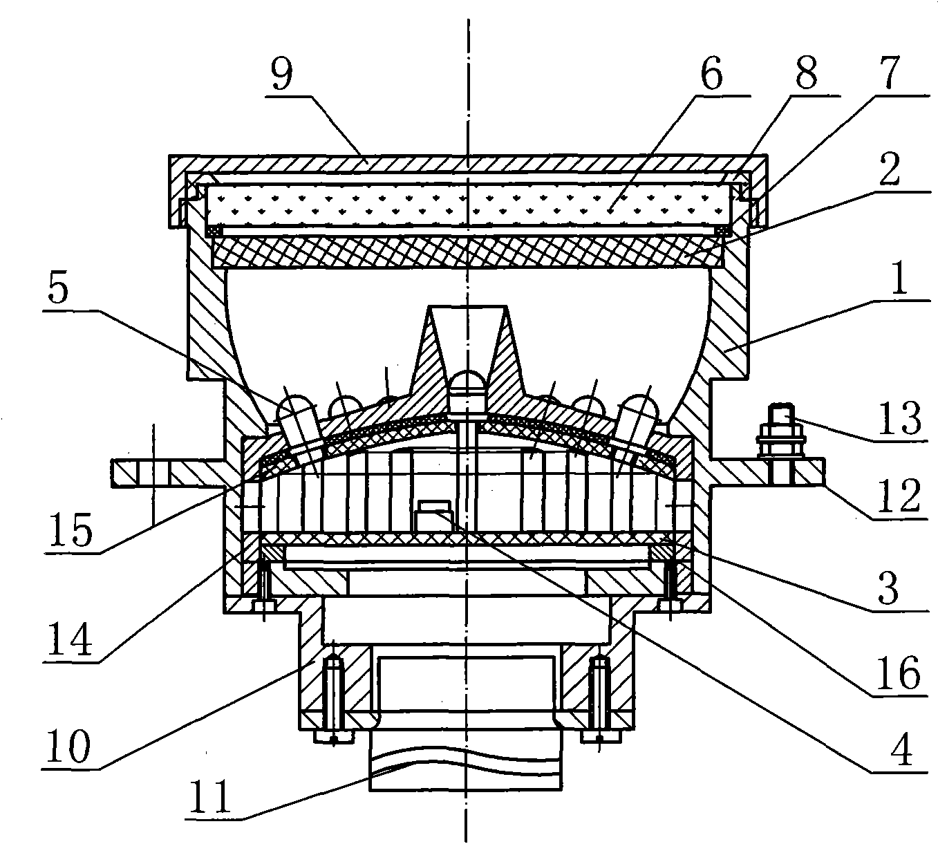
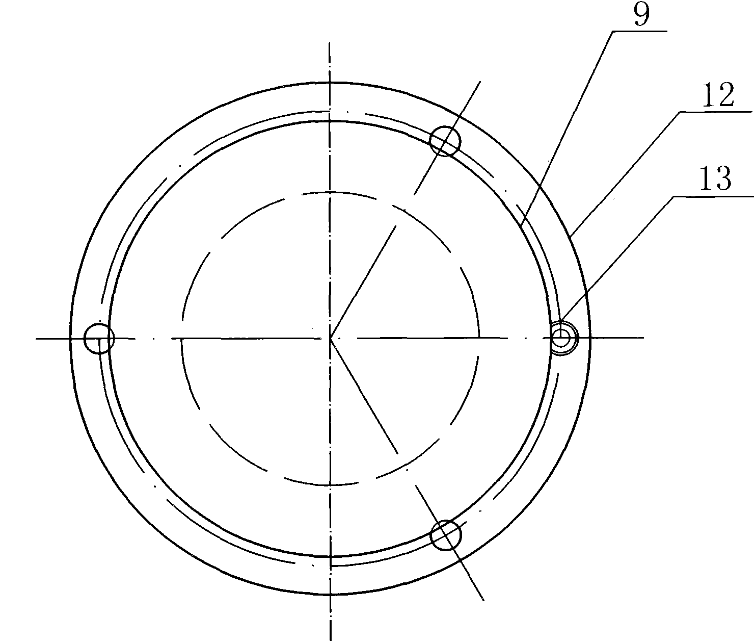
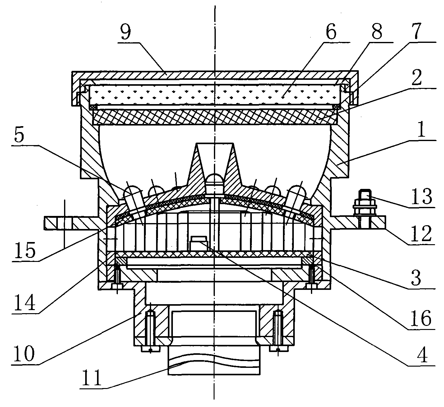
[0040] The far-field target marker consists of: a cylindrical housing 1, the front section of the cylindrical housing is equipped with a high-uniformity optical fiber panel 2, and the rear section of the cylindrical housing is equipped with a light-emitting combination, The light-emitting combination includes a circuit board 3 on which a thermistor 4 and a group of near-infrared light-emitting diodes 5 are connected.

[0041] An application of an optical fiber panel to a far-field target marker.

Embodiment 2

[0043] In the far-field target marker, the light-emitting device is a light-emitting diode

Embodiment 3

[0045]In the far-field target marker, the light-emitting devices are arranged in such a way that one light-emitting device is installed in the center, and the rest of the light-emitting devices are installed in a circular layout around the central light-emitting device and between the axial direction and the axial direction of the central light-emitting device. have a certain inclination angle.


PUM


Abstract

The invention provides a far-field target marker and application of an optical fiber panel. The structural design of the marker used at present cannot guarantee single peaks, smoothness and symmetry of a radiation beam, and is difficult to guarantee a given radiation angle; in the absence of reinforcing designs of elimination of the sunshine effect, high and low temperature resistance and radiation resistance, the conventional marker cannot meet the requirements of a far distance and a large range, and cannot normally work in strong interference environments with sunshine and other stray lights, environments of large variation of high and low temperature, and environments with intense radiation. The far-field target marker comprises a cylindrical shell (1); the front section of the cylindrical shell is provided with a high-uniformity optical fiber panel (2), and the rear section of the cylindrical shell is provided with a light-emitting combination; and the light-emitting combination comprises a circuit board (3) which is connected with a thermistor (4) and a group of near infrared light-emitting diodes (5). The far-field target marker is used as an active optical cooperative target or an active light source mark in a large distance range, and can be widely applied to fields of aviation, spaceflight, airports, docks, traffic hinges and the like.

Description

Technical field: [0001] The invention relates to a far-field target marker and the application of the optical fiber panel thereof. Background technique: [0002] Far-field target marker, as an active optical cooperative target or active light source marker with a large distance range, has a larger range of action than passive optical (target) markers. At present, light-emitting diodes (LEDs) are mostly used as light sources, and lasers are also used. Diodes (LDs). However, if LDs are used as the light source, not only complex thermal control equipment is required, but the stability is poor, and it is difficult to meet the requirements of a larger radiation angle because of its small divergence angle. The light source of the far-field target marker is LEDs / IREDs, which does not require complex temperature control equipment, and can easily guarantee the advantages of high stability, long life, small size, light weight and low power consumption, and its divergence angle can be...

Claims


Application Information

Patent Timeline
Patent Type & Authority Applications(China)
IPC IPC(8): G09F13/22F21S8/00F21V5/00F21V15/02F21V23/00F21V17/00F21Y101/02F21Y115/10
Inventor 李金宗李冬冬朱兵杨学峰马冬冬
Owner 李金宗
Learn More