
Novel tact switch assembling machine

A light touch switch and assembly machine technology, which is applied in the direction of electric switches, electrical components, circuits, etc., can solve the problems of long running route of manipulators, inconvenient assembly and assembly, and affecting quality, so as to facilitate reciprocation, fast installation, and improve efficiency Effect

Inactive Publication Date: 2011-06-15
周俊雄
View PDF7 Cites 49 Cited by
  • Summary
  • Abstract
  • Description
  • Claims
  • Application Information

AI Technical Summary

Problems solved by technology

The above-mentioned manual assembly of light touch switch components is labor-intensive, low in production efficiency, prone to substandard products, and affects quality. Therefore, the manual assembly method is far from meeting the needs of production development.
[0003] In order to solve this problem, some automatic tact switch assembly machines have also appeared on the market at present, as Chinese patent 200910214578.6 discloses a kind of tact switch automatic assembly machine, but, in the described assembly machine, each assembly station uses The linear transfer mechanism is adopted, so the entire assembly machine occupies a large space, and it is not convenient to assemble and assemble repeatedly, and the efficiency is relatively low
In addition, the manipulator used to realize the automation process also adopts the common vertical and horizontal driving methods separately, that is, after the manipulator grabs the workpiece, it first rises vertically, moves horizontally to the top of the target, and then descends. The workpiece is placed at the target place. In such a process, the manipulator runs a long route, takes a long time, and is extremely inefficient

Method used


Image

  • Novel tact switch assembling machine
  • Novel tact switch assembling machine
  • Novel tact switch assembling machine

Examples


Embodiment Construction

[0039] The present invention will be further described below in conjunction with specific examples, but the specific examples do not limit the present invention in any way.

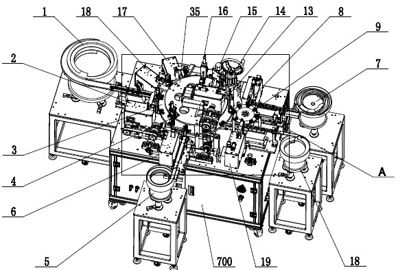
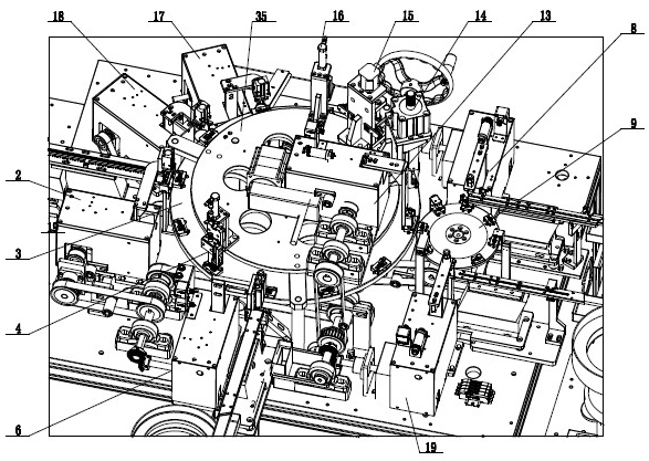
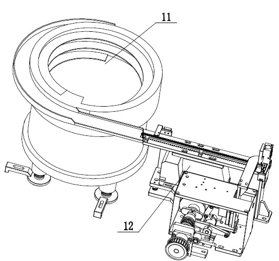
[0040] Such as figure 1 , 2 As shown, the new light touch switch assembly machine in the present invention includes: a body 700 and a large rotating disk assembly 3 and a small rotating disk assembly 9 arranged on the body 700 . Along the counterclockwise circumferential direction of the large rotating disk assembly 3, there are sequentially arranged: sending body vibration disk assembly 1, upper body manipulator assembly 2, foreign object removal assembly 4, upper shrapnel manipulator assembly 6, shrapnel sending vibration disk assembly 5, assembly manipulator assembly 13. A pressing component 14 , a CLICR detection component 15 , a conduction detection component 16 , a good product manipulator component 17 and a defective product manipulator component 18 . Among them, the assembly manipulator componen...


PUM


Abstract

The invention discloses a novel tact switch assembling machine which comprises a machine body, a manipulator assembly and a feeding assembly, wherein the manipulator assembly and the feeding assembly are arranged on the machine body. The novel tact switch assembling machine also comprises a large turntable assembly and a small turntable assembly, which are sequentially arranged on the machine body; a compaction assembly is also arranged on the large turntable assembly; the manipulator assembly is used for sequentially placing a body and an elastic sheet on the feeding assembly at corresponding positions on the large turntable assembly, sequentially placing a button and an iron sheet on the feeding assembly at corresponding positions on the small turntable assembly and sequentially assembling a button and an iron sheet on the small turntable onto the elastic sheet of the large turntable; the compaction assembly is used for sequentially compacting the body, the elastic sheet, the buttonand the iron sheet on the large turntable assembly; and all assemblies are connected with and controlled by a master control circuit. Through the novel tact switch assembling machine of the invention, the automatic assembling of a tact switch can be realized, the occupied space is small, the running efficiency is high and the assembling can be realized rapidly.

Description

technical field [0001] The invention relates to a novel automatic assembling machine for light touch switches, which is used to automatically feed, assemble and detect light touch switch components composed of a body, elastic pieces, buttons and iron pieces. Background technique [0002] Due to its small size and light weight, tact switches are widely used in household appliances, such as TV buttons, DVD player buttons, computer mice, mobile phone buttons, and so on. However, in the prior art, the assembly of the tact switch is done by hand. Ordinary manpower assembly is generally divided into two stations. The first station is to assemble the body and the shrapnel, and the shrapnel is sucked up with a suction pen and loaded into the body. middle; the other station is to assemble buttons and iron sheets; then the parts assembled by station 1 and station 2 are sent to the press machine for final assembly. The above-mentioned manual assembly of tact switch components is labor...

Claims


Application Information

Patent Timeline
IPC IPC(8): H01H11/00
Inventor 周俊雄周俊豪周俊杰
Owner 周俊雄
Learn More