Automatic production line for connectors and production technology of automatic production line

An automatic production line and connector technology, which is applied in manufacturing tools, welding equipment, metal processing, etc., can solve the problem of inability to realize the automatic production of grid electrical connectors, and achieve the effect of simple fixing method, improved efficiency and smooth connection.

Active Publication Date: 2020-06-05
广州贝兴电子科技有限公司
View PDF13 Cites 10 Cited by
  • Summary
  • Abstract
  • Description
  • Claims
  • Application Information

AI Technical Summary

Problems solved by technology

[0004] The purpose of the present invention is to provide an automatic connector production line to solve the technical problem that the automatic production of grid electrical connectors cannot be realized in the prior art

Method used


Image

  • Automatic production line for connectors and production technology of automatic production line
  • Automatic production line for connectors and production technology of automatic production line
  • Automatic production line for connectors and production technology of automatic production line

Examples


Embodiment 1

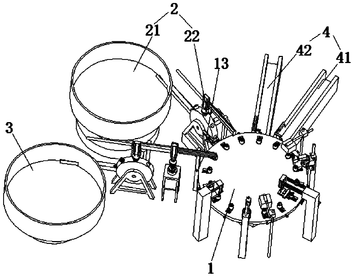
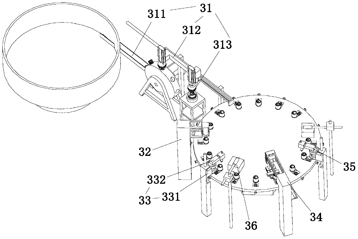
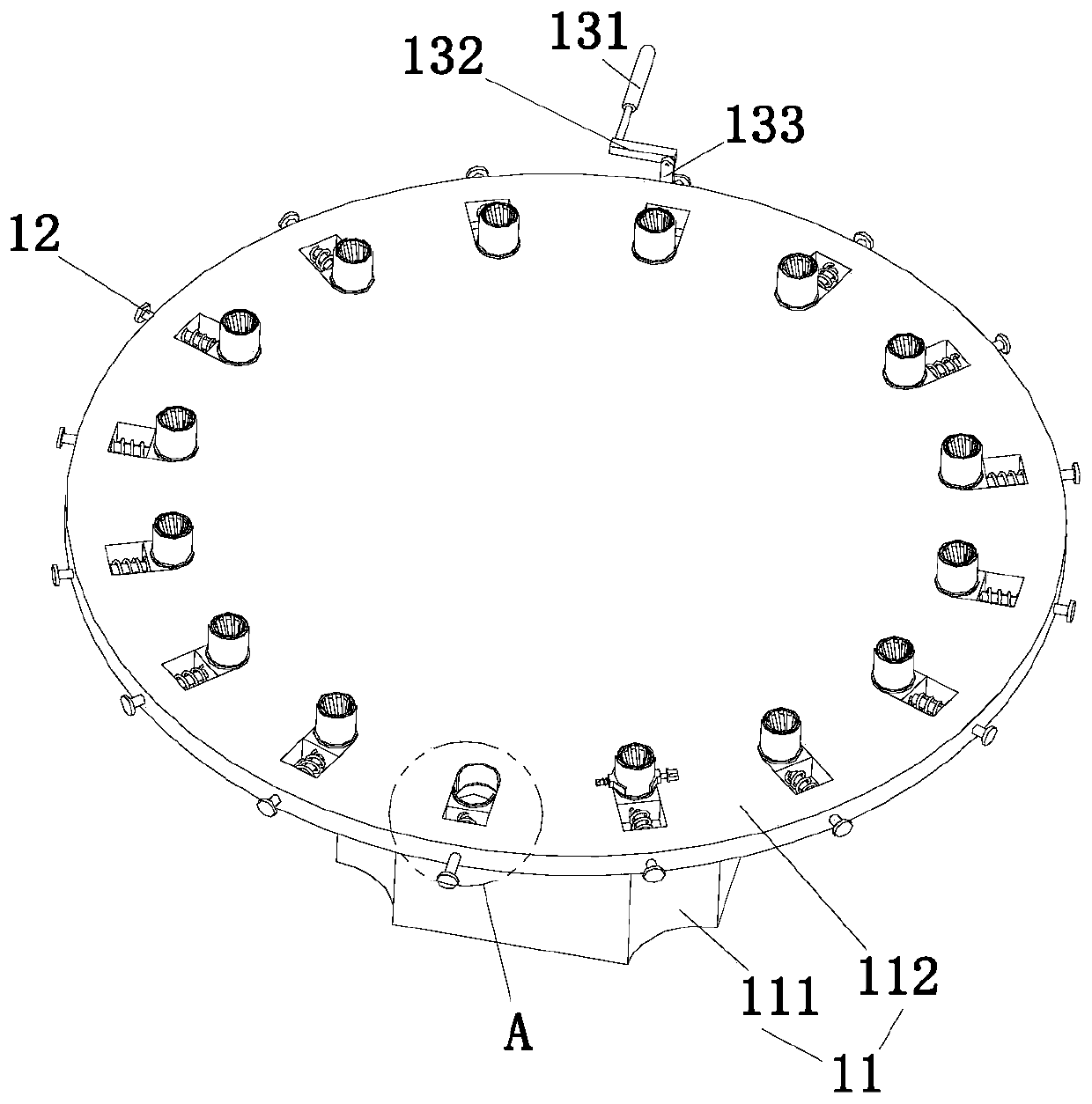
[0039] Combine below Figure 1 to Figure 11 As shown, the embodiment of the present invention provides an automatic production line for connectors, including a rotary transport mechanism 1, a feeding mechanism 2, an assembly mechanism 3 and a blanking mechanism 4, and the loading mechanism 2, the assembly mechanism 3 and the blanking mechanism 4 are in the form of The circumference is distributed on the side of the rotary transport mechanism 1. The rotary transport mechanism 1 includes a rotary assembly 11, a fixed assembly 12 and a push-pull assembly 13 matched with the fixed assembly 12. The fixed assembly 12 is provided with several, and several fixed Components 12 are circumferentially distributed on the upper end of the rotating component 11. The feeding mechanism 2 includes a sleeve feeding component 21 and a sleeve moving component 22. The sleeve feeding component 21 is arranged on the side of the rotating component 11, so The sleeve moving assembly 22 is arranged betwe...

Embodiment 2

[0058] The production process of the connector automatic production line described in embodiment 1 includes the following steps:

[0059] Step 1. First, vibrate the feeding tray 211 through the sleeve so that the sleeves are conveyed sequentially along the sleeve feeding channel 212, and the sleeve at the end of the sleeve feeding channel 212 is delivered to the corresponding sleeve feeding chute 216 on the feeding block Inside, the sleeve feeding motor 214 works to drive the sleeve feeding block 215 to rotate until the sleeve in the sleeve feeding groove 216 is rotated to a vertical state, and the lifting cylinder 224 works to move the three-jaw chuck 226 to the vertical position. At the upper end of the sleeve, the three-jaw chuck 226 clamps the sleeve, and then the moving cylinder 223 works to push the moving block 225 to move along the moving guide rod 222, and then the sleeve is carried to the corresponding fixed component 12;

[0060] Step 2. Afterwards, the lifting cyli...


PUM


Abstract

The invention discloses an automatic production line for connectors, and relates to the technical field of production of the connectors. The automatic production line comprises a rotating transportation mechanism, a feeding mechanism, an assembling mechanism and a discharging mechanism; the feeding mechanism, the assembling mechanism and the discharging mechanism are circumferentially distributedon the side of the rotating transportation mechanism; the rotating transportation mechanism comprises a rotating component, a plurality of fixing components and a push-and-pull component matched withthe fixing components; the plurality of fixing components are circumferentially distributed at the upper end of the rotating component; the feeding mechanism comprises a sleeve feeding component and asleeve moving component; the sleeve feeding component is arranged on the side of the rotating component; and the sleeve moving component is arranged between the sleeve feeding component and the rotating component. According to the automatic production line, automatic assembling and welding production of the grid electrical connectors is realized, step-by-step processing by the aid of multiple devices is not required, manual product moving steps and positioning steps are reduced, and thus the production efficiency of the grid electrical connectors is improved effectively.

Description

technical field [0001] The invention relates to the technical field of connector production, in particular to an automatic connector production line and a production process thereof. Background technique [0002] Connectors are the basic components of important electrical connections and signal transmission in electronic equipment. They have the characteristics of good contact, reliable operation and convenient maintenance. [0003] Chinese patent No. CN202474316U discloses a sleeve-type laser welding connector terminal, which mainly includes a sleeve and a grid, and the two ends of the sleeve and the grid are welded by laser. However, in the prior art, it is necessary to use separate grid twisting and laser welding equipment for step-by-step processing when producing such connector terminals. Accessories positioning processing. In this process, on the one hand, automatic production cannot be realized, which reduces production efficiency; on the other hand, manual operatio...

Claims


Application Information

Patent Timeline
Patent Type & Authority Applications(China)
IPC IPC(8): B23P19/027B23K26/21B23P19/00
CPCB23P19/001B23P19/027B23K26/21
Inventor 李水华
Owner 广州贝兴电子科技有限公司
Why Eureka
Try Eureka