Electronic element rubber pipe and rubber plug assembly machine

A technology for electronic components and rubber stoppers, applied in the field of automatic assembly equipment and automatic equipment, can solve the problems of high labor cost, low work efficiency, inconvenient overall operation, etc., and achieve the effect of improving conveying efficiency and high degree of automation

Inactive Publication Date: 2018-11-02
广州市速波光电科技有限公司
View PDF7 Cites 10 Cited by
  • Summary
  • Abstract
  • Description
  • Claims
  • Application Information

AI Technical Summary

Problems solved by technology

[0004] Since the assembly process of the rubber plug and the transparent packaging tube is very simple, there are two ways to assemble the rubber plug and the transparent packaging tube. One is to assemble directly by manual operation. The advantage of manual assembly is that it does not need to purchase any equipment Simple assembly is possible, while manual assembly has the disadvantages of low work efficiency and high labor costs; the other is assembly by semi-automatic assembly equipment, the existing semi-automatic assembly equipment has a simple structure, including rubber plugs for placing rubber plugs The jig and the tube jig used to place the transparent packaging tube are then assembled by manual operation. Each simple assembly equipment requires an operator to operate. The advantage of this semi-automatic assembly equipment is that the assembly efficiency is relatively high. The disadvantage is that the operator is still required to carry out loading, unloading, assembly and unloading, the overall operation is inconvenient, and some human resources need to be invested

Method used


Image

  • Electronic element rubber pipe and rubber plug assembly machine
  • Electronic element rubber pipe and rubber plug assembly machine
  • Electronic element rubber pipe and rubber plug assembly machine

Examples


Embodiment Construction

[0033] The present invention will be further described in detail below in conjunction with the accompanying drawings and specific embodiments.

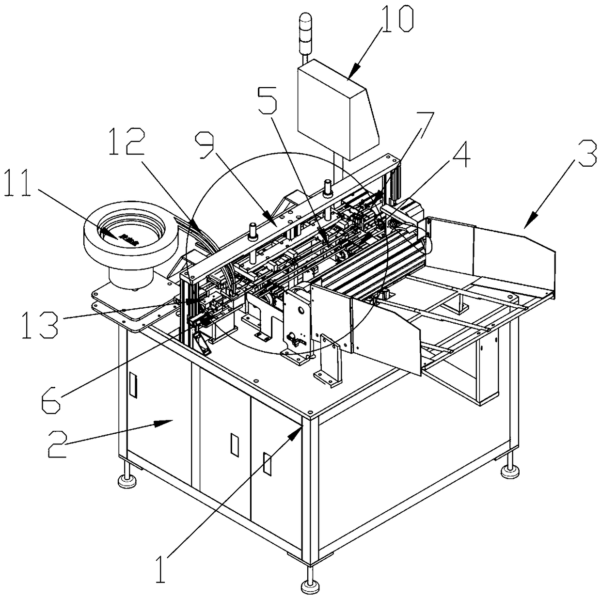
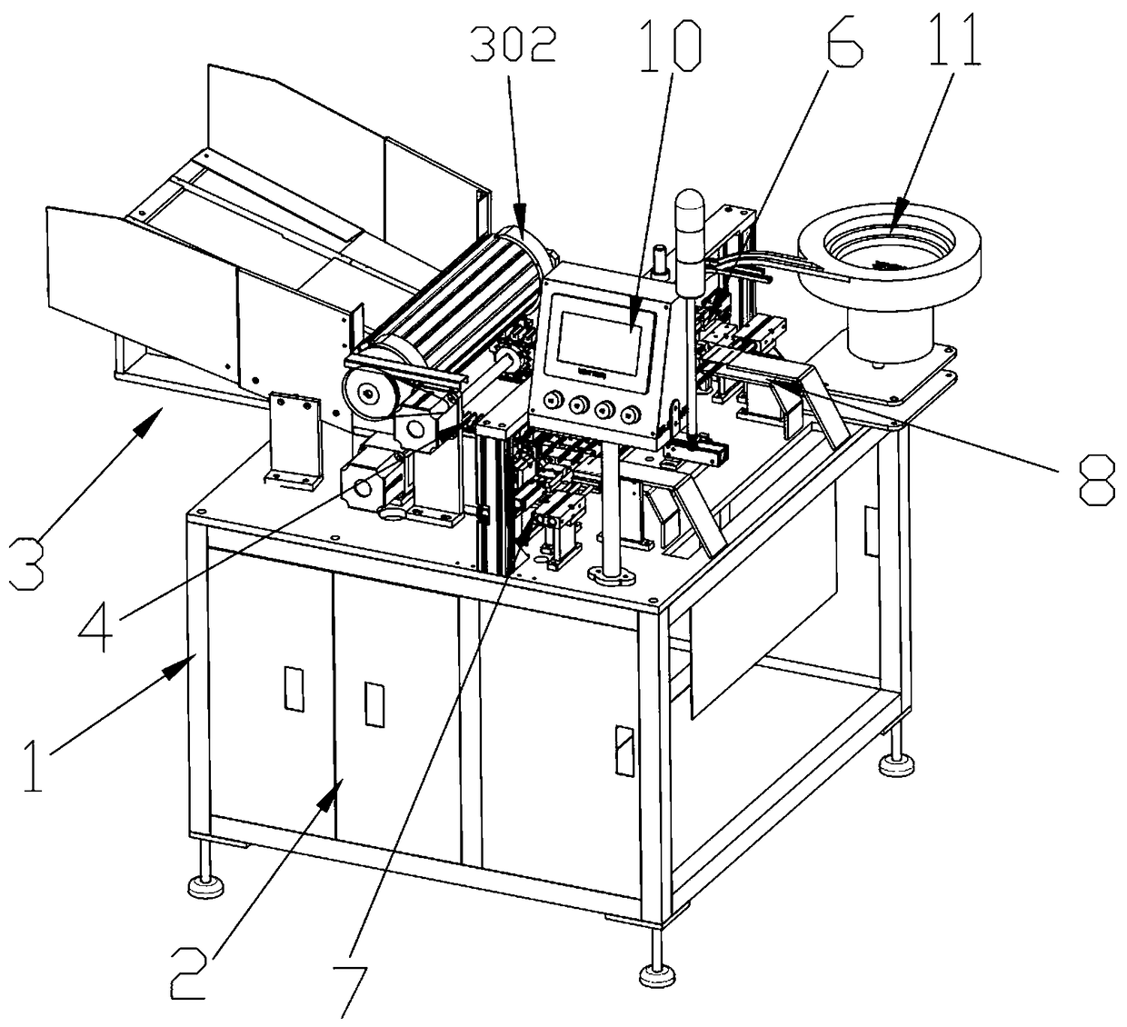
[0034] In this embodiment, refer to Figure 1-Figure 9 , the electronic component hose rubber plug assembly machine specifically implemented, including a frame 1 and an automatic assembly platform arranged on the top of the frame 1, the inside of the frame 1 is provided with a main control distribution cabinet 2, and the top of the frame 1 is provided with The man-machine switchboard 10 electrically connected with the main control distribution cabinet 2 .

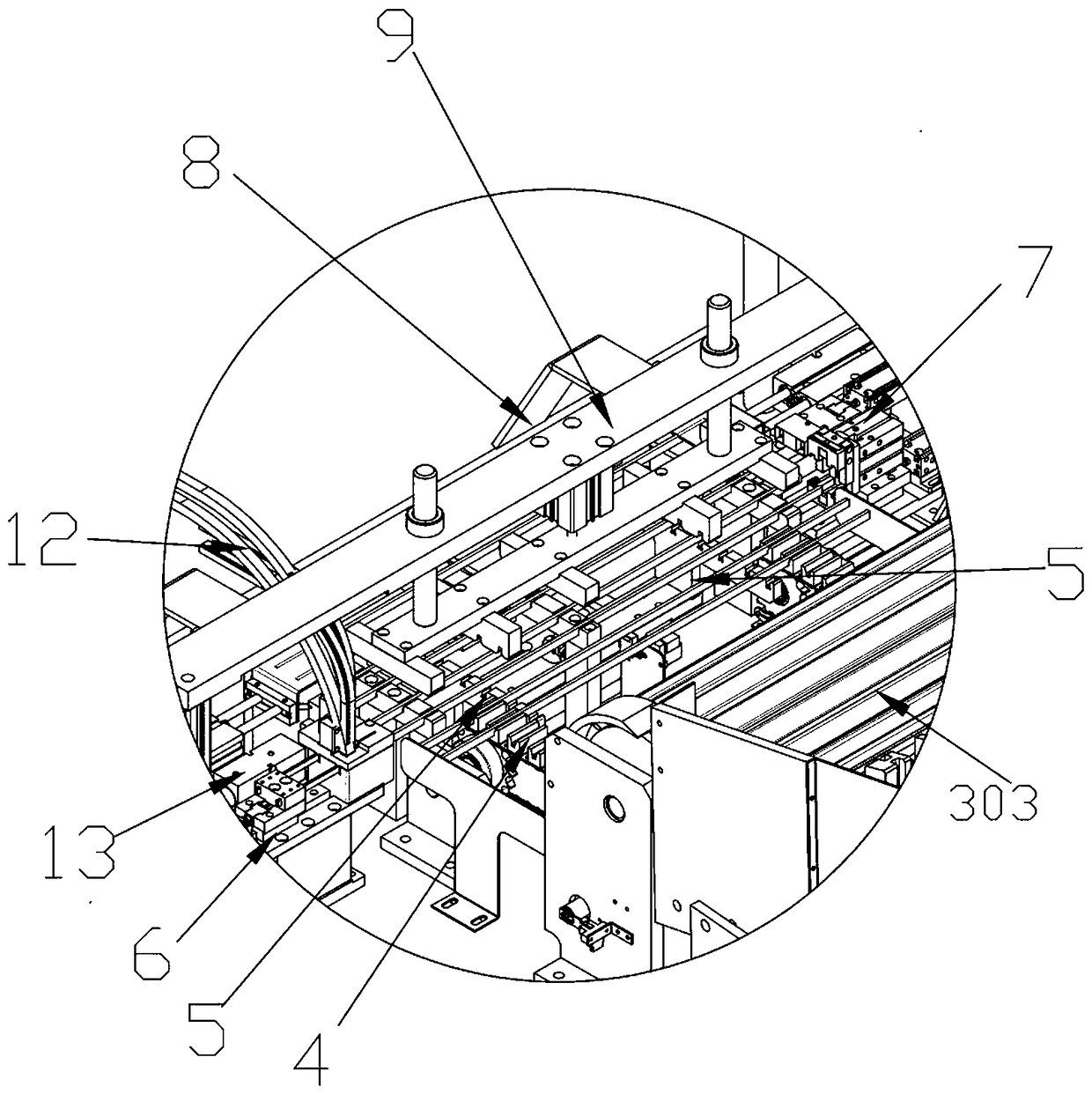
[0035] Such as Figure 4 and Figure 5 As shown, the automatic assembly platform includes a hose unloading mechanism 3, a hose conveying mechanism 4, a rubber plug unloading mechanism 6, a hose rear end positioning mechanism 7, a material shifting mechanism 5 and a discharging mechanism 8, and the hose conveying mechanism 4 is arranged under the hose Behind the material mechanis...


PUM


Abstract

The invention relates to an electronic element rubber pipe and rubber plug assembly machine in the field of automatic equipment. The machine comprises a frame, and an automatic assembly platform arranged at the top of the frame; the automatic assembly platform comprises a rubber pipe unloading mechanism, a rubber pipe conveying mechanism, a rubber plug unloading mechanism, a rubber pipe back end positioning mechanism, a shifting mechanism and a discharge mechanism; the shifting mechanism can be directly adopted to synchronously realize receiving, shifting and discharge actions, so that more shifting structures can be saved, and the overall structure is simple; compared with traditional manual assembly, an automatic production line is used for operating to realize automatic feeding, automatic assembly and automatic discharge, so that the working efficiency is high, the rejection rate is lower, and a lot of labor costs can be saved; the whole assembly process is precise in positioning; packing pipes are positioned from all directions; real-time detection can be realized after assembly; and precise assembly and precise detection can be realized through automatic machinery.

Description

technical field [0001] The invention relates to the field of automation equipment, in particular to the field of automatic assembly equipment. Background technique [0002] Electronic component hoses are IC, integrated circuits, integrated blocks, semiconductors, electronic components, transformer parts and precision electronic components and packaging pipes. They are mainly used as packaging materials to prevent damage to parts during transportation and during transportation. A packaging tube that prevents electrostatic damage to components caused by static electricity. [0003] The electronic component hose is composed of a transparent packaging tube body and a rubber plug. One end of the transparent packaging tube body is a sealed end, and the rubber plug is paired into the other end of the transparent packaging tube body. Put the components into the transparent packaging tube, and then put on the rubber plug to play a good protective effect. On the contrary, directly re...

Claims


Application Information

Patent Timeline
Patent Type & Authority Applications(China)
IPC IPC(8): B23P19/00
CPCB23P19/00B23P19/001
Inventor 宋思宁
Owner 广州市速波光电科技有限公司
Why Eureka
Try Eureka