Cutting device

A cutting device and cutting fluid technology, which is applied in the direction of fine working devices, electrical components, semiconductor/solid device manufacturing, etc., can solve the problems of unstable suction state and hinder the suction of cutting fluid, and achieve the purpose of enhancing the suction force Effect

Active Publication Date: 2011-06-15
DISCO CORP
View PDF5 Cites 7 Cited by
  • Summary
  • Abstract
  • Description
  • Claims
  • Application Information

AI Technical Summary

Problems solved by technology

[0008] However, even if the suction source is intended to suck the cutting fluid as disclosed in Patent Document 1, there is a problem that the air sucked by the suction source together with the cutting fluid hinders the suction of the cutting fluid, and the suction state unstable

Method used


Image

  • Cutting device
  • Cutting device
  • Cutting device

Examples


Embodiment Construction

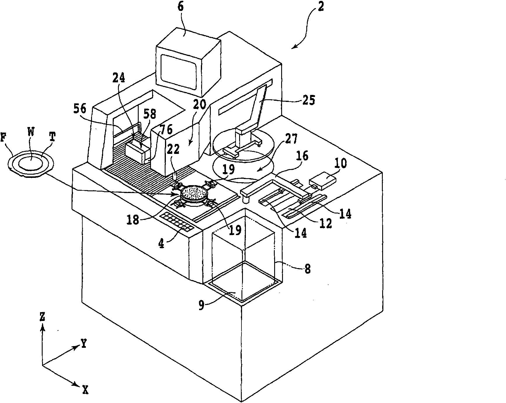
[0022] Hereinafter, embodiments of the present invention will be described in detail with reference to the drawings. figure 1 The appearance of the cutting device 2 according to the embodiment of the present invention is shown. On the front side of the cutting device 2 is provided an operating member 4 for an operator to input instructions to the device such as machining conditions. A display unit 6 such as a CRT (Cathode Ray Tube: Cathode Ray Tube) for displaying a guidance screen for an operator or an image captured by an imaging unit described later is provided on the upper part of the device.

[0023] Reference numeral 8 denotes a wafer cassette, and a plurality of (for example, 25) semiconductor wafers supported by a ring frame via dicing tapes are accommodated in the wafer cassette 8 . The wafer cassette 8 is placed on a cassette elevator 9 capable of moving up and down.

[0024] Arranged behind the wafer cassette 8 is an unloading and loading member 10 that unloads th...


PUM


Abstract

The invention provides a cutting device, which enables a stable suction of cutting liquid and applies no damage to an object to be processed. The cutting device comprises a sucking mouth disposed at flying side of the cutting liquid along with the rotation of the cutting tool, an inflow channel connected to the sucking mouth, a fluid separating mechanism body which comprises a first opening, a second opening and a third opening, wherein the third opening is disposed at the same height as the first opening or at the position lower than the first opening for discharging the cutting liquid, a suction source connected to the second opening, and a discharge channel with one end being connected to the third opening and the other end being provided with a discharging outlet whose height is equal to or lower than that of the first opening. The discharge channel discharges the liquid in the fluid separating mechanism body and is provided with a liquid accumulation part which enables the discharging outlet to be full of liquid all the time and prevent external gas from flowing in.

Description

technical field [0001] The present invention relates to a cutting device including: a cutting tool for cutting a workpiece; and a cutting fluid supply member for supplying cutting fluid to the cutting tool. Background technique [0002] In the manufacturing process of semiconductor devices, a plurality of devices such as IC (Integrated Circuit: Integrated Circuit), LSI (Large-scale Integration: Large-Scale Integration) or solid-state imaging devices are formed on the surface of a semiconductor wafer. Then, the wafer is divided into individual devices by cutting the wafer with a cutting device along planned dividing lines called lanes that divide the individual devices. [0003] As the cutting device, what is called a dicer is widely used, and the dicer includes a cutting member including a cutting blade. A cutting tool has a cutting edge made of superhard abrasive grains such as diamond or CBN (Cubic Boron Nitride: cubic boron nitride) fixed by metal or resin, and has a thi...

Claims


Application Information

Patent Timeline
Patent Type & Authority Applications(China)
IPC IPC(8): H01L21/78B28D5/00
Inventor 迈克尔・威廉姆・加德
Owner DISCO CORP
Why Eureka
Try Eureka