Solar thin-film cell and manufacture method thereof

A solar thin film and thin film battery technology, applied in circuits, photovoltaic power generation, electrical components, etc., can solve the problems of low output power, low voltage and current of solar cells, etc.

Inactive Publication Date: 2011-06-15
ARCHERS
View PDF5 Cites 0 Cited by
  • Summary
  • Abstract
  • Description
  • Claims
  • Application Information

AI Technical Summary

Problems solved by technology

[0005] Traditional thin-film solar cells use P-type doped silicon and N-type doped silicon to form a PN junction. However, the energy band gap of silicon is only 1.1 to 1.9 electron volts (eV), so the built-in The electric field is low, and the low electric field will make the output voltage and current low, which makes traditional solar cells have low output power limitations

Method used


Image

  • Solar thin-film cell and manufacture method thereof
  • Solar thin-film cell and manufacture method thereof
  • Solar thin-film cell and manufacture method thereof

Examples


Embodiment Construction

[0035] In order to enable those skilled in the art to further understand the present invention, several preferred embodiments of the present invention are listed below, together with the accompanying drawings, the composition and beneficial effects of the present invention are described in detail.

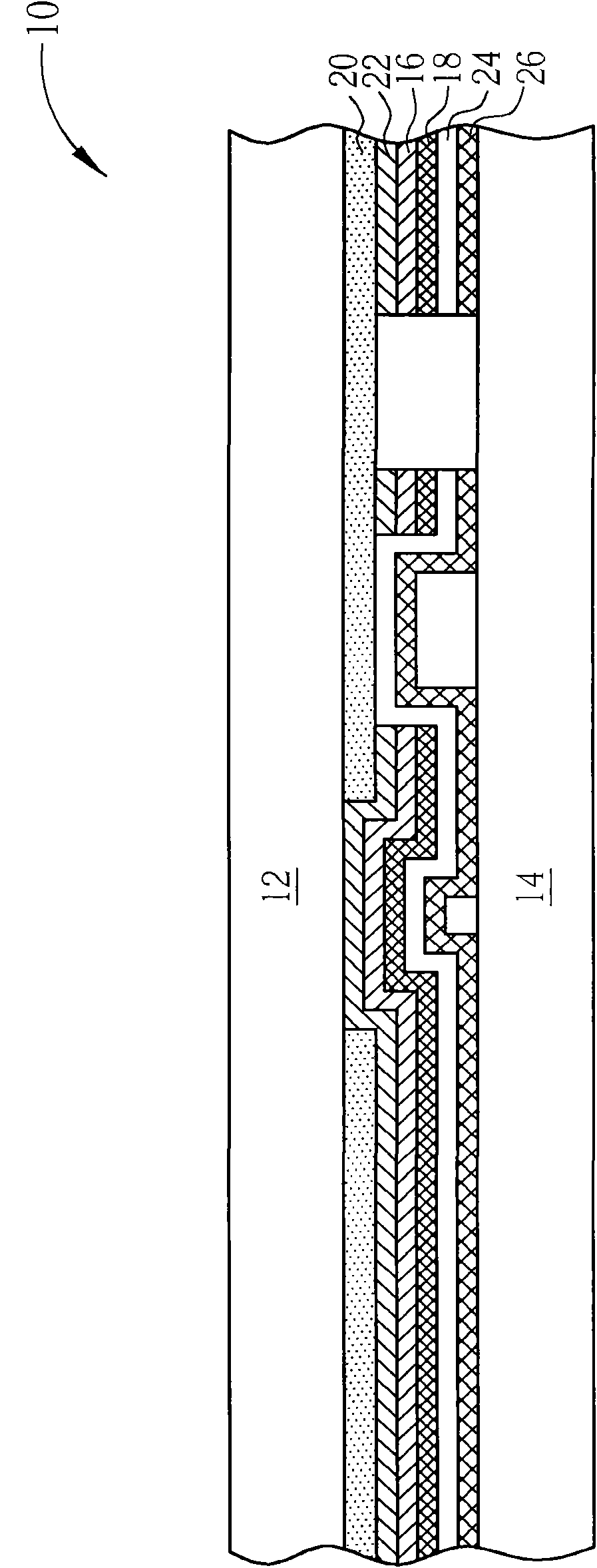
[0036] Please refer to figure 1 . figure 1 It is a schematic diagram of the solar thin film battery according to the first preferred embodiment of the present invention. Such as figure 1 As shown, the solar thin film battery 10 of the present embodiment includes a first substrate 12, a second substrate 14, an intrinsic (intrinsic) semiconductor layer 16, an N-type doped semiconductor layer 18, a P-type doped polycrystalline A diamond (P doped poly crystalline diamond) layer 20 , a P-type doped semiconductor layer 22 , a first transparent conductive layer 24 and a reflective electrode 26 . In this embodiment, the first substrate 12 and the second substrate 14 are substantially pa...


PUM


Abstract

The invention relates to a solar thin-film cell comprising a first substrate, a second substrate, an intrinsic semiconductor layer, an N-type doped semiconductor layer and a P-type doped polycrystalline diamond layer. The second substrate and the first substrate are oppositely arranged, the intrinsic semiconductor layer is arranged between the first substrate and the second substrate, the N-type doped semiconductor layer is arranged between the intrinsic semiconductor layer and the second substrate, and the P-type doped polycrystalline diamond layer is arranged between the first substrate and the intrinsic semiconductor layer. In the invention, the solar thin-film cell is internally provided with the P-type doped polycrystalline diamond layer and a built-in electric field is enhanced by utilizing the high energy gap characteristic of the P-type doped polycrystalline diamond layer so as to improve the output power of the solar thin-film cell.

Description

Technical field: [0001] The invention relates to a solar thin-film battery and a manufacturing method thereof, in particular to a high-output solar thin-film battery and a manufacturing method thereof. Background technique: [0002] At present, the energy used by human beings mainly comes from petroleum resources. However, due to the limited petroleum resources on the earth, the demand for alternative energy sources has been increasing day by day in recent years. Among the various alternative energy sources, solar energy has the greatest potential for development. [0003] The main principle of solar cells is to convert light energy into electrical energy, and there are two main factors why solar cells can convert light energy into electrical energy: one is the photoconductive effect, and the other is the built-in electric field. field). When electrons get energy from the outside world, they will jump to a higher energy level. The more energy they get, the higher the energy...

Claims


Application Information

Patent Timeline
Patent Type & Authority Applications(China)
IPC IPC(8): H01L31/042H01L31/028H01L31/18H01L31/0445
CPCY02E10/50Y02E10/547Y02P70/50
Inventor 杨国玺李春生赖政志游萃蓉
Owner ARCHERS
Why Eureka
Try Eureka