
Voltage stabilization method applied to output of piezoelectric transformer

A piezoelectric transformer and voltage stabilizing technology, applied in the direction of output power conversion device, AC power input conversion to DC power output, electrical components, etc., can solve the problems of poor product reliability, high cost, and inability to meet product miniaturization, etc.

Inactive Publication Date: 2011-06-15
MORNSUN GUANGZHOU SCI & TECH
View PDF6 Cites 2 Cited by
  • Summary
  • Abstract
  • Description
  • Claims
  • Application Information

AI Technical Summary

Problems solved by technology

The disadvantage of using this voltage stabilization method is that the control method is complicated, the cost is high, the product reliability is relatively poor, and it cannot meet the requirements of product miniaturization.

Method used


Image

  • Voltage stabilization method applied to output of piezoelectric transformer
  • Voltage stabilization method applied to output of piezoelectric transformer
  • Voltage stabilization method applied to output of piezoelectric transformer

Examples

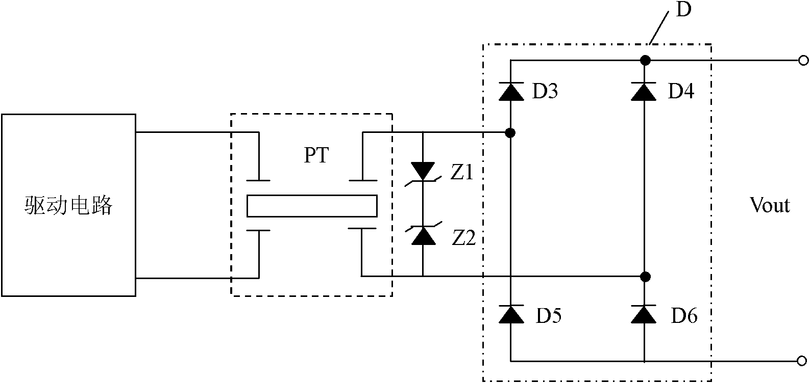

Embodiment Construction

[0024] figure 2 It is an application block diagram of a piezoelectric transformer using the method of the present invention, including an input filter circuit, a drive circuit, a piezoelectric transformer PT, output rectification and output voltage stabilization, a filter circuit and a load. By connecting at least one voltage stabilizing diode working in the reverse breakdown voltage stabilizing region at the output end of the piezoelectric transformer or in the rectification circuit output by the piezoelectric transformer, a voltage stabilizing loop connected in parallel with the output load is formed to realize a voltage stabilizing output.

[0025] image 3 It is the circuit diagram of the first embodiment of the piezoelectric transformer output voltage stabilizing method of the present invention. As shown in the figure, the voltage stabilizing circuit is composed of two voltage stabilizing diodes Z1 and Z2 whose cathodes are connected, and are directly connected to the ou...


PUM


Abstract

The invention discloses a voltage stabilization method applied to output of a piezoelectric transformer. At least one voltage stabilizing diode which works in a reverse breakdown voltage stabilization area is connected at an output end of the piezoelectric transformer or to a rectification circuit of the output of the piezoelectric transformer, so that a voltage stabilization loop connected in parallel with an output load is formed to realize voltage stabilization output. The circuit structure is simple, and the output load regulating capacity of the piezoelectric transformer can be improved; therefore, the requirement on product miniaturization can be met.

Description

technical field [0001] The invention relates to a method for stabilizing voltage at an output terminal; in particular, it relates to a method for stabilizing voltage suitable for the output of a piezoelectric transformer. Background technique [0002] Piezoelectric ceramic transformer is a new type of piezoelectric transducer, which has the advantages of small size, simple structure, non-combustibility, radiation resistance, no electromagnetic interference, built-in short-circuit protection, and high reliability. It is currently an ideal device that can replace electromagnetic transformers. However, when the piezoelectric transformer is open-loop, the output load regulation ability is poor, and the output voltage has a poor output load regulation rate, which cannot be used in occasions with large load changes. [0003] The block diagram of the working principle of the existing common piezoelectric transformer output voltage stabilization method is as follows: figure 1 As s...

Claims


Application Information

Patent Timeline
IPC IPC(8): H02M7/219
Inventor 邓维体黄天华
Owner MORNSUN GUANGZHOU SCI & TECH
Learn More