Optical syntropic fault detection device and operating method thereof

A detection device and coherence technology, applied in the field of optical detection, can solve problems such as bulky, optical path difference, and increased cost of optical coherence tomography detection devices, and achieve the effects of reduced manufacturing costs and simplified architecture

Inactive Publication Date: 2011-06-22
RAYDIUM SEMICON +1
View PDF0 Cites 2 Cited by
  • Summary
  • Abstract
  • Description
  • Claims
  • Application Information

AI Technical Summary

Problems solved by technology

[0008] Whether it is figure 1 or figure 2 The optical coherence tomography detection devices in the present invention all need to rely on a translation or rotation mechanical structure to achieve the effect of generating optical path difference, which will not only increase the cost of the optical coherence tomography detection device, but also make the structure of the optical coherence tomography detection device more complex. complex, and potentially bulky

Method used


Image

  • Optical syntropic fault detection device and operating method thereof
  • Optical syntropic fault detection device and operating method thereof
  • Optical syntropic fault detection device and operating method thereof

Examples


Embodiment Construction

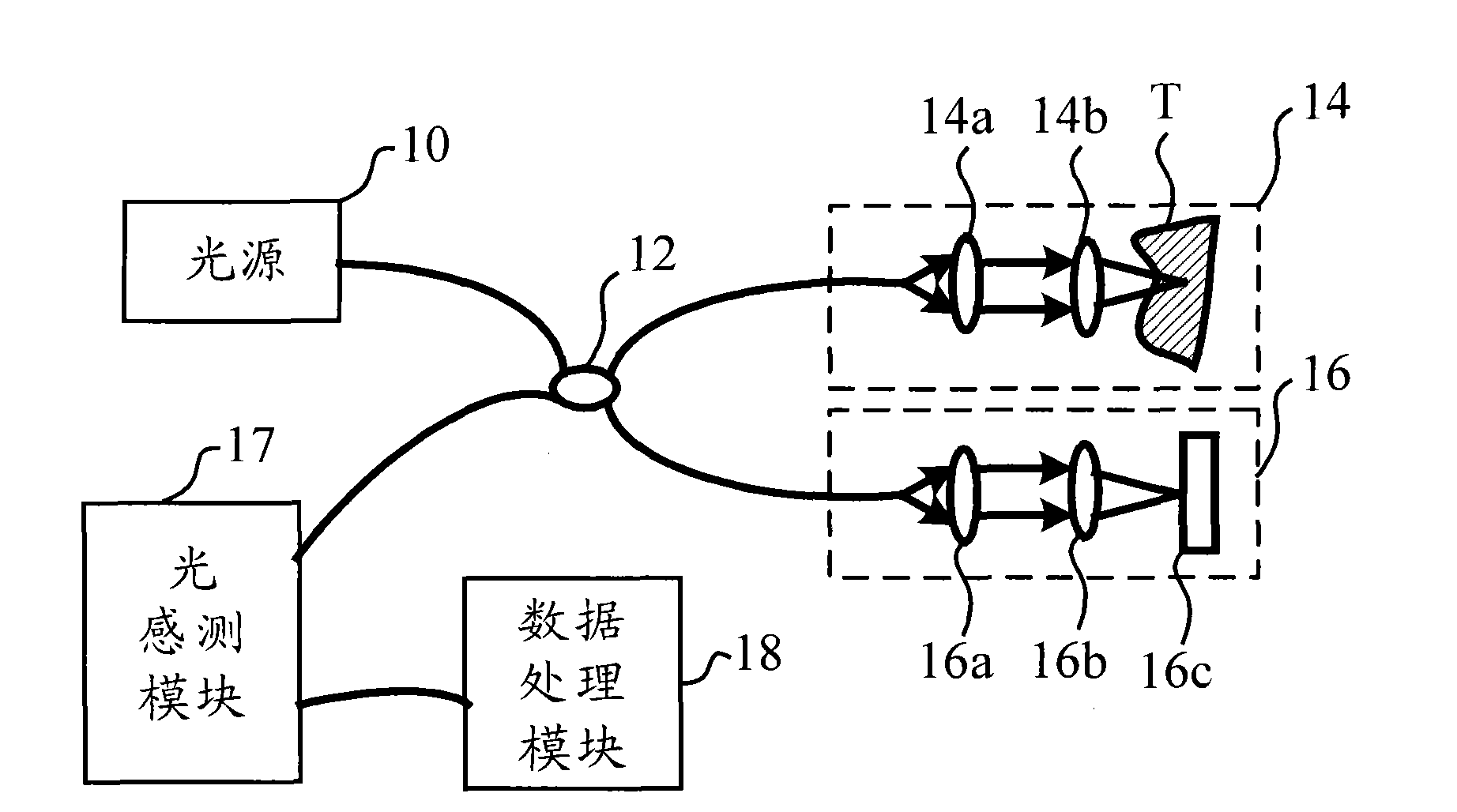
[0041] The first specific embodiment according to the present invention is an optical coherence tomography detection device. In this embodiment, the optical coherence tomography detection device is used to detect an object under test, thereby obtaining optical data about a vertical section of the object under test. Please refer to image 3 , image 3 A functional block diagram of the optical coherence tomography detection device is shown.

[0042] Such as image 3 As shown, the optical coherence tomography detection device 2 includes a light source 20 , an optical coupling module 22 , an optical path difference generating module 24 , a sample module 26 , an optical sensing module 28 and a processing module 30 . Wherein, the optical coupling module 22 is coupled to the optical sensing module 28 ; the optical sensing module 28 is coupled to the processing module 30 . In addition, the light source 20 is a coherent light source; the optical coupling module 22 is a beam splitte...


PUM


Abstract

The invention provides an optical syntropic fault detection device, which comprises a light source, an optical coupling module and an optical path difference generating module. The light source is used for emitting syntropic light. The optical coupling module is used for dividing the syntropic light into first incident light and second incident light. The first incident light is shot to an objectto be tested so as to generate reflected light; the second incident light is shot to the optical path difference generating module; and the optical path difference generating module generates second reflected light according to the second incident light in a mode of changing transmission / reflection characters of at least one optical element, so that an optical path difference exists between the second reflected light and the first reflected light. The invention also provides an operating method of the optical syntropic fault detection device.

Description

technical field [0001] The present invention relates to optical detection, in particular to an optical coherence tomography detection device capable of providing effects of optical path difference and optical frequency change without using a mechanical structure and an operation method thereof. Background technique [0002] In recent years, with the continuous advancement of optical detection technology, optical image scanning technology provides a non-invasive method to understand the structure and composition of the target tissue. Due to its fast and non-invasive characteristics, this type of technology has considerable Wide range of applications, especially in medical diagnosis. When light is incident into the tissue structure, the absorption and scattering properties of the light will also change with the change of the medium at different depths. Optical image scanning is to use various optical methods to obtain the information carried by the inside of the tissue and the...

Claims


Application Information

Patent Timeline
Patent Type & Authority Applications(China)
IPC IPC(8): A61B5/00
Inventor 周忠诚王威
Owner RAYDIUM SEMICON
Why Eureka
Try Eureka