Supercharge Your Innovation With Domain-Expert AI Agents!

a/b mode detection circuit for adaptive field strength change

A field strength change, detection circuit technology, applied in the direction of induction record carriers, instruments, computer parts, etc., can solve the problem of inability to recognize A/B mode signals, and achieve the effect of enhancing adaptability

Active Publication Date: 2014-10-15
SHANGHAI HUAHONG INTEGRATED CIRCUIT
View PDF6 Cites 0 Cited by
  • Summary
  • Abstract
  • Description
  • Claims
  • Application Information

AI Technical Summary

Problems solved by technology

As mentioned earlier, non-contact IC cards or radio frequency identification tags need to be able to identify whether the signal sent by the reader-writer belongs to mode A or mode B within the entire required field strength range, so that there will be a situation, namely: large field The modulation amplitude of the B-mode signal when the field strength is strong is greater than that of the A-mode signal when the field strength is small. If the recognition ability of the A / B mode detection circuit is the same under the large and small field strength, it will not be able to detect the signal in the entire field strength range. Identify A / B mode signals

Method used


Image

  • a/b mode detection circuit for adaptive field strength change
  • a/b mode detection circuit for adaptive field strength change

Examples


Embodiment Construction

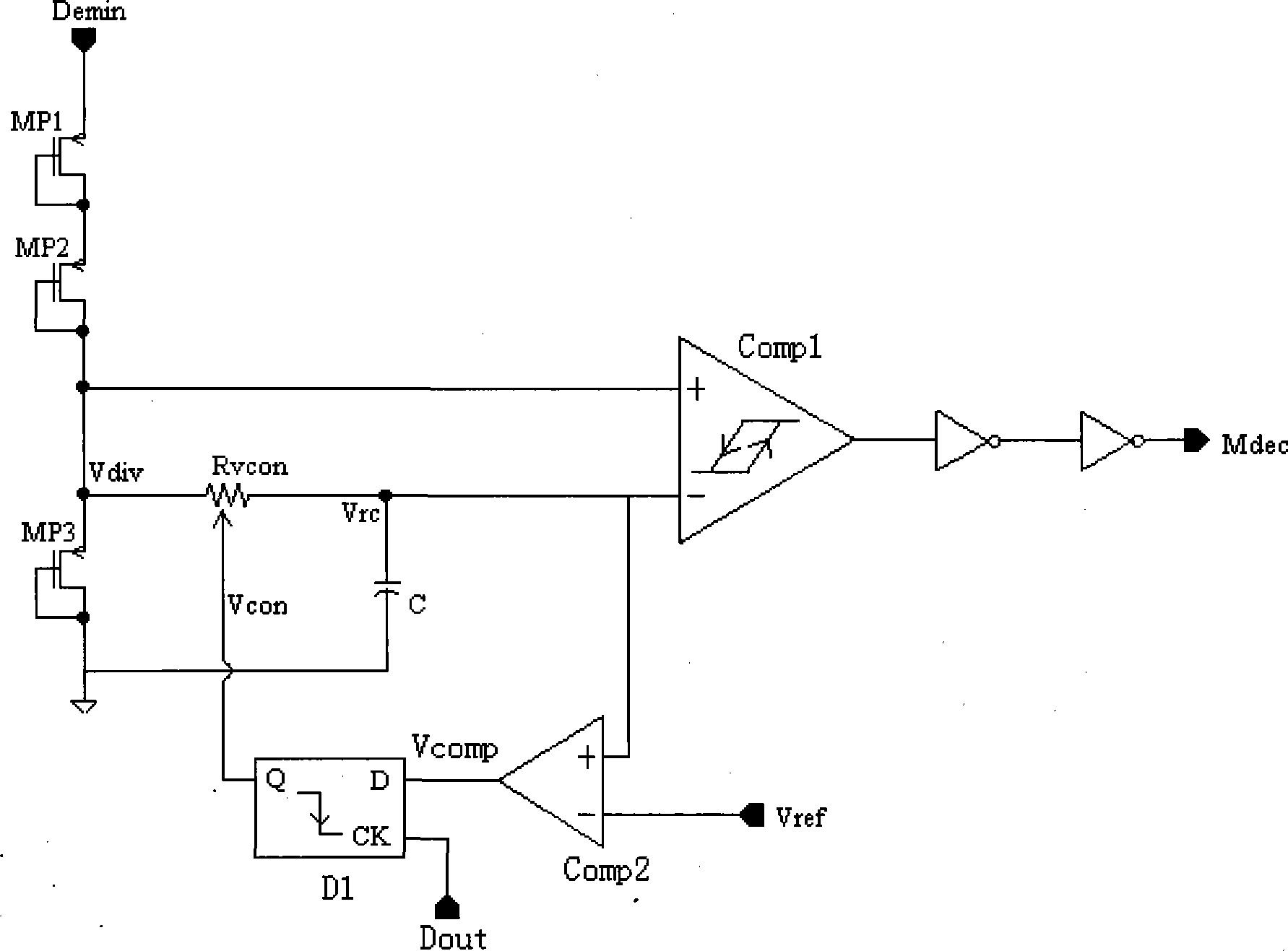
[0012] Such as figure 2 As shown, when the AC carrier signal sent by the reader to the space is coupled by the antenna end of the non-contact IC card or RFID tag and sent to the rectification and filtering circuit, the output signal is generated, that is, the DC envelope signal Demin. The envelope signal Demin contains the amplitude modulation information of the signal sent by the reader. At the place of amplitude modulation, the envelope signal will have a groove; at the same time, the amplitude of the envelope signal Demin is directly related to the non-contact IC card or radio frequency identification. The field strength of the tag is related. The larger the field strength is, the higher the envelope signal Demin amplitude is, and the smaller the field strength is, the lower the envelope signal Demin amplitude is.

[0013] The envelope signal Demin is sent to a voltage-dividing bias circuit composed of MP1, MP2, and MP3 connected in the form of diodes to generate a voltage...


PUM


Abstract

The invention discloses an A / B mode detection circuit adaptive to variation of field intensity. The circuit comprises a voltage division biasing circuit, an RC (resistance-capacitance) filtering circuit, a hysteresis comparison circuit and a voltage detection circuit, wherein the voltage division biasing circuit is used for detecting an input signal envelope; the RC filtering circuit is used for filtering a voltage division signal obtained by the voltage division biasing circuit to obtain an RC filtering signal; a resistor in the RC filtering circuit is a voltage controlled resistor; the hysteresis comparison circuit is used for obtaining the output of A / B mode detection through the voltage division signal and the RC filtering signal; and the voltage detection circuit is used for detecting the amplitude of the RC filtering circuit, sampling through a D trigger triggered by a failing edge, adjusting the resistance value of the voltage controlled resistor in the RC filtering circuit and adjusting an RC filtering parameter according to a sampling result, wherein a trigger signal of the D trigger triggered by the failing edge is a data signal output by a demodulation circuit. By adopting the A / B mode detection circuit, the detection capability of a mold detection circuit can be adjusted in a self-adaptive way according to field intensity, so that an A / B mode signal can be effectively and reliably recognized in an entire required field intensity range. The A / B mode detection circuit is suitable for a non-contact IC (Integrated Card) and a radio frequency identification tag.

Description

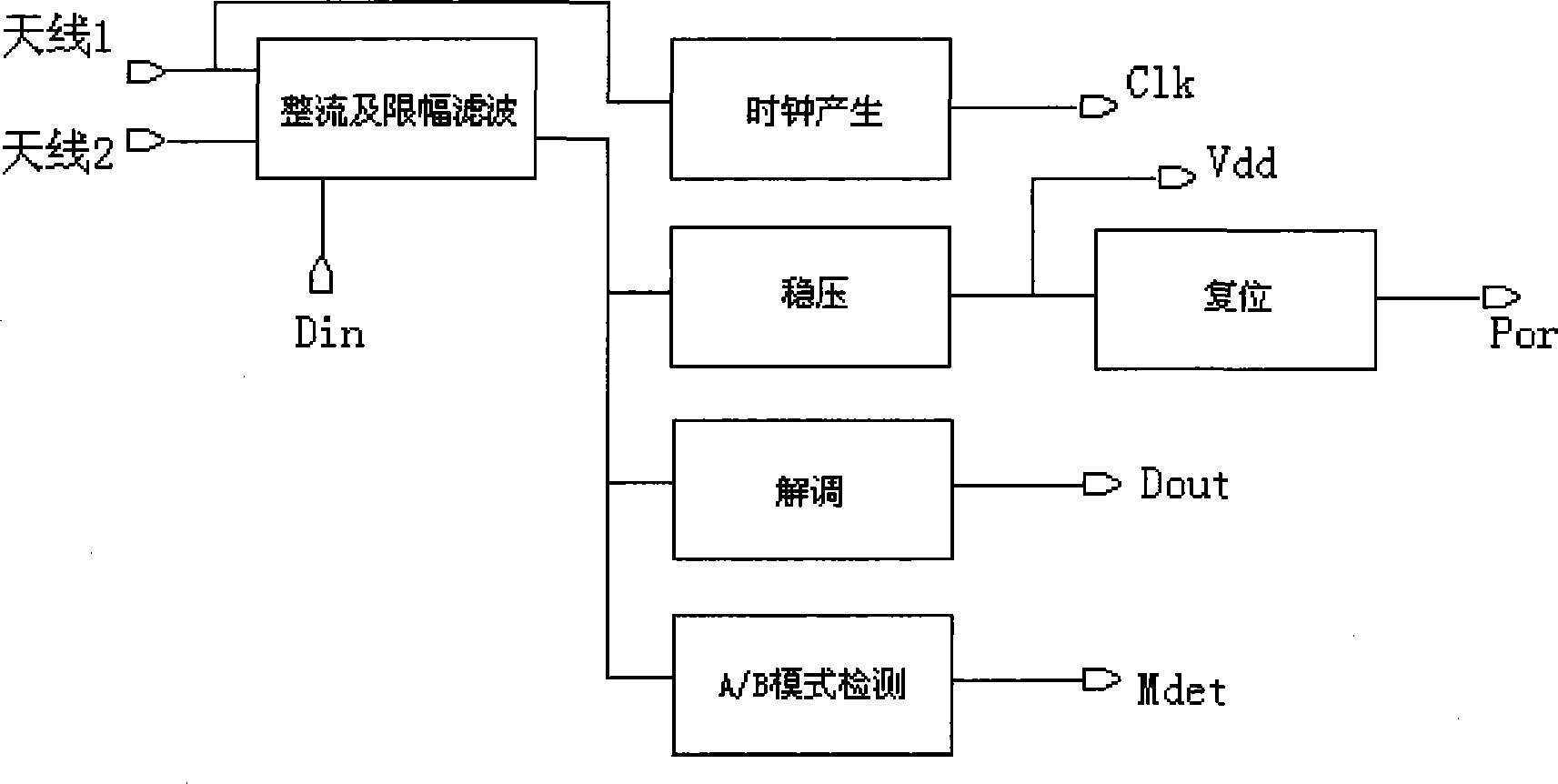
technical field [0001] The invention relates to a mode detection circuit, in particular to an A / B mode detection circuit which adapts to changes in field strength. Background technique [0002] At present, non-contact IC cards or radio frequency identification tags commonly used in industries such as subways, public transportation, identity authentication, logistics, and tickets are gradually replacing traditional paper tickets and have more and more applications. [0003] The non-contact IC card or radio frequency identification tag system includes two parts: a reader and a non-contact IC card or radio frequency identification tag chip. [0004] figure 1 It shows the functional circuit required by the internal radio frequency interface of the non-contact IC card or RFID tag in order to complete the normal communication between the reader-writer and the non-contact IC card or RFID tag. Among them, on the one hand, the rectification and limiting filter circuit converts the ...

Claims


Application Information

Patent Timeline
Patent Type & Authority Patents(China)
IPC IPC(8): G06K7/00
Inventor 刘曙斌刘颖赵林春
Owner SHANGHAI HUAHONG INTEGRATED CIRCUIT
Features
  • R&D
  • Intellectual Property
  • Life Sciences
  • Materials
  • Tech Scout
  • Unparalleled Data Quality
  • Higher Quality Content
  • 60% Fewer Hallucinations
Learn More