Switch structure and associated circuit

一种机电开关、整流电路的技术,应用在电路、电开关、电子开关等方向,能够解决泄漏电流、功率耗散、开关性能和寿命有害等问题

Active Publication Date: 2011-06-22
GENERAL ELECTRIC CO
View PDF3 Cites 8 Cited by
  • Summary
  • Abstract
  • Description
  • Claims
  • Application Information

AI Technical Summary

Problems solved by technology

However, because solid state switches do not create a physical gap between the contacts when switched into the non-conductive state, they experience leakage currents when nominally non-conductive
Furthermore, solid-state switches operating in the conductive state experience a voltage drop due to internal impedance
Both voltage drop and leakage current contribute to power dissipation and overheating under normal operating conditions, which can be detrimental to switch performance and lifetime
Also, at least in part due to the inherent leakage currents associated with solid state switches, it is impossible to use solid state switches in circuit breaker applications

Method used


Image

  • Switch structure and associated circuit
  • Switch structure and associated circuit
  • Switch structure and associated circuit

Examples


Embodiment Construction

[0090] Example embodiments of the present invention are described in detail below with reference to the accompanying drawings, in which like reference numerals refer to like parts throughout. Some of these embodiments can address the above and other needs.

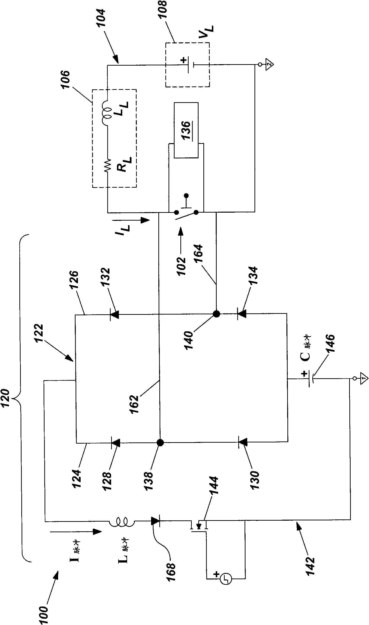
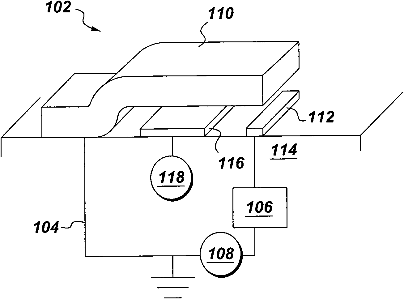
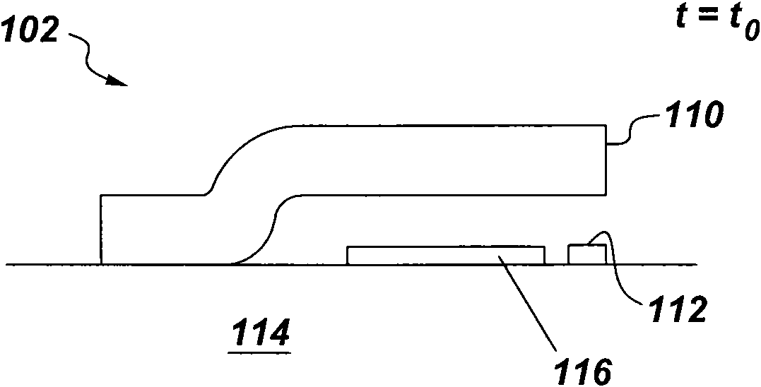
[0091] refer to figure 1 , wherein an apparatus constructed in accordance with an example embodiment is shown, such as a switch module 100 (eg, for use in conjunction with a motor starter application). The switch module 100 may include an electromechanical switch structure, such as a microelectromechanical switch or a microelectromechanical system (MEMS) switch 102 . The MEMS switch 102 may be incorporated as part of a load circuit 104 which also includes, for example, a load inductance L L and load resistor R L The electrical load 106 is characterized. Note that the load circuit 104 may also include inherent inductance and resistance, and these will affect the effective load inductance L L and load resistor R L and ...


PUM


Abstract

An apparatus, such as a switch module (100), is provided. The apparatus can include an electromechanical switch structure (102) configured to move between an open configuration and a fully-closed configuration (associated with a minimum characteristic resistance) over a characteristic time. A commutation circuit (120) can be connected in parallel with the electromechanical switch structure, and can include a balanced diode bridge (122) configured to suppress arc formation between contacts of the electromechanical switch structure and a pulse circuit (142) including a pulse capacitor (146) configured to form a pulse signal (in connection with a switching event of the electromechanical switch structure) for causing flow of a pulse current through the balanced diode bridge. The electromechanical switch structure and the balanced diode bridge can be disposed such that a total inductance associated with the commutation circuit is less than or equal to a product of the characteristic time and the minimum characteristic resistance.

Description

technical field [0001] Embodiments of the invention relate generally to devices for switching electrical current, and more particularly to microelectromechanical switch structures. Background technique [0002] A circuit breaker is an electrical device designed to protect electrical equipment from damage caused by a fault in an electrical circuit. Traditionally, many conventional circuit breakers include bulky (macro) electromechanical switches. Unfortunately, these conventional circuit breakers are large in size and may have to use relatively large forces to actuate the switching mechanism. Additionally, the switches of these circuit breakers typically operate at relatively low speeds. Furthermore, these circuit breakers can be complex to construct and thus expensive to manufacture. Additionally, when the contacts of a switching mechanism in a conventional circuit breaker physically separate, an arc can sometimes form between the contacts, which allows current to continu...

Claims


Application Information

Patent Timeline
Patent Type & Authority Applications(China)
IPC IPC(8): H01H59/00
CPCH01H59/0009H01H9/542H01H1/0036H01H2071/008H03K17/687
Inventor A·V·高达K·A·奥布里恩J·N·帕克W·J·普里默拉尼O·J·S·谢伦茨K·苏布拉马尼安
Owner GENERAL ELECTRIC CO
Why Eureka
Try Eureka