Electric locomotive device system for generating and charging by vacuum energy

An electric locomotive and vacuum technology, applied in the direction of generators/motors, electromechanical devices, electric vehicles, etc., can solve the problems of self-charging, etc., and achieve the effects of easy storage, easy implementation and popularization, and low price

Inactive Publication Date: 2011-06-22
上海兆锟光电科技有限公司 +2
View PDF0 Cites 1 Cited by
  • Summary
  • Abstract
  • Description
  • Claims
  • Application Information

AI Technical Summary

Problems solved by technology

[0002] The current electric vehicles need to be recharged after parking, or the battery pack needs to be replaced, and they cannot be self-charged when parking or driving

Method used


Image

  • Electric locomotive device system for generating and charging by vacuum energy
  • Electric locomotive device system for generating and charging by vacuum energy
  • Electric locomotive device system for generating and charging by vacuum energy

Examples


Embodiment 1

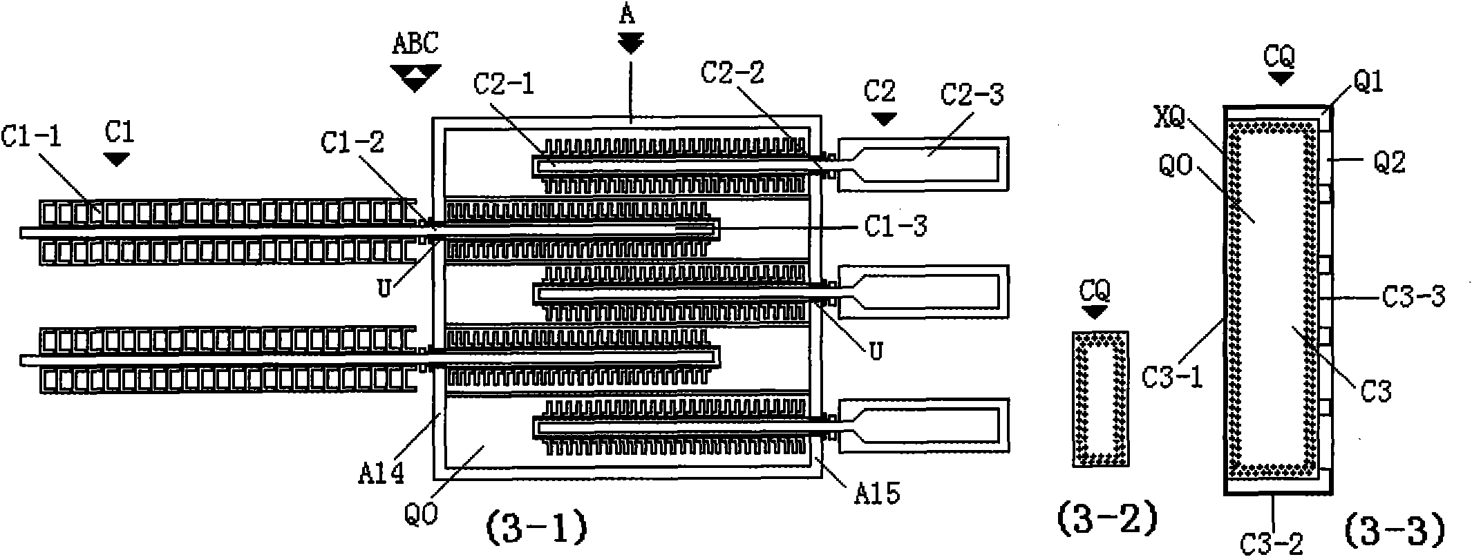
[0107] exist figure 1 , 2 , 3 middle: heat source box (A), vacuum shell (A10), vertical hole spacer (A11), casing hole (A12), casing hole (A13), front box plate (A14), rear box plate ( A15), rectangular vacuum energy pump (CQ); vacuum energy storage heat source box (AB), casing (U), nut seat (U1), internal thread (U2), U-shaped tube (U0), fin (U0L / Z), heat gathering source box (A), vacuum energy liquid (Q0); rectangular pump (CQ), heat gathering source vacuum energy pump box (ABC), heat gathering source box (A), heat gathering source vacuum energy pump (C1), Heat source vacuum energy pump (C2), vacuum shell pump (C3), energy gathering end (C1-1), energy gathering end (C2-1), energy gathering end (C3-1), energy transmission section (C1-2 ), energy transmission section (C2-2), energy transmission section (C3-2), energy dissipation end (C1-3), energy dissipation end (C2-3), energy dissipation end (C3-3), bushing ( U), front box plate (A14), rear box plate (A15), rectangular v...

Embodiment 2

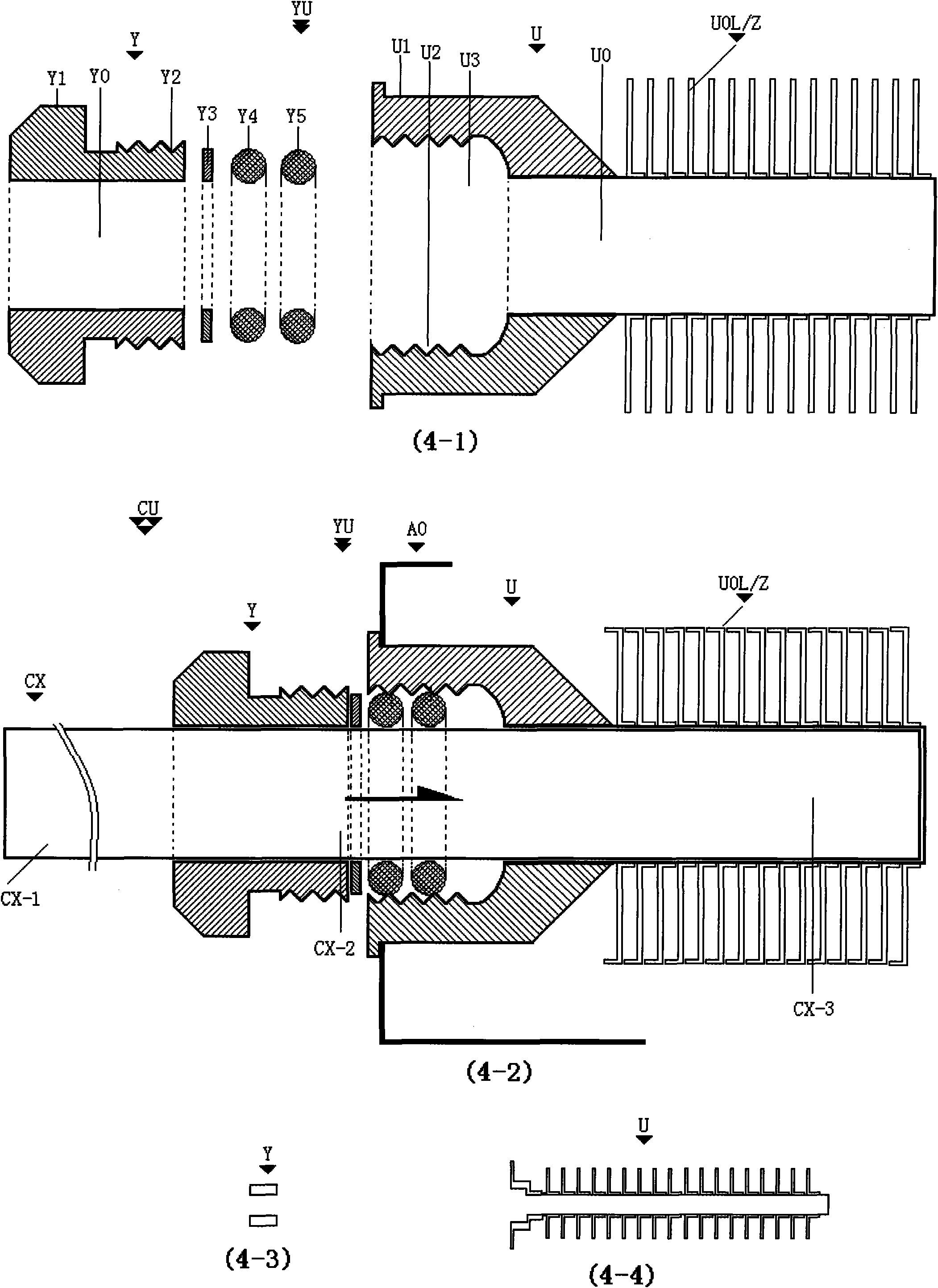
[0114] exist Figure 4 Middle: pump casing (YU), pump bolt (Y), round hole (Y0), bolt handle (Y1), external thread (Y2), gasket (Y3), rubber ring (Y4), rubber ring (Y5), Sleeve (U), nut seat (U1), internal thread (U2), inner hole (U3), U-shaped tube (U0), fins (U0L / Z), vacuum energy pump (CX), energy gathering end ( CX-1), energy transmission section (CX-2), energy dissipation end (CX-3), outer box tube (A0).

[0115] In the figure: the pump casing (YU) consists of the casing (U) connected by the pump pin (Y);

[0116] The pump bolt (Y) is composed of a bolt handle (Y1) with a round hole (Y0) and an external thread (Y2); and a gasket (Y3), an apron (Y4), and an apron sleeve (Y5) are used in the vacuum energy pump (CX) outside the energy gathering end (CX-1), energy transmission section (CX-2) or energy dissipation end (CX-3);

[0117] The sleeve (U) is connected by a U-shaped tube (U0) connected by a nut seat (U1) with an inner hole (U3) and an internal thread (U2) and a fi...

Embodiment 3

[0120] exist Figure 5 , 6 , 7 and 8: bushing heat accumulation box (AB), rectangular vacuum energy pump (CQ), vacuum shell (Q1), concave frame (Q2), convex frame (Q3), vacuum energy liquid (Q0), Sintering layer (XQ), heat-gathering vacuum energy pump (C), energy-gathering end (C-1), energy transmission section (C-2), energy-dissipating end (C-3), vacuum energy liquid (Q0), sintering Layer (XQ), Comb Right Angle (LE1), Comb Right Angle (LE2), Casing Heat Collector Box (AB), Back Box Plate (A15), Energy Isolation Surface (QQ); Vertical Pump (CQC1), Single Soft Pump (CQC2), double soft pump (CQC2), pump vacuum shell (QQ), energy transmission section (CQC-2), energy gathering end (CQC-1), hose section (CS), hose section (CS1), Hose section (CS2); type 3 pump generator (CQ-3A), type 6 pump generator (CQ-3B), vacuum energy pump (CQC), energy transmission section (CQC-2), pump hole (Q0) , pump generator (CQ-3B), vacuum shell (Q1), concave frame (Q2), convex frame (Q3), rear end (...


PUM


Abstract

The invention discloses an electric locomotive device system for generating and charging by vacuum energy. The device consists of a heat source pump box, a pump generator, an accelerator, a magnetic vacuum generator, a friction generating device, an S-shaped air flow power pipe, an impeller, a dual-generating device and a computer control system, wherein the heat source pump box is connected with the pump generator, then is connected with the dual-generating device formed by the magnetic vacuum generator, the friction generating device and the S-shaped air flow power pipe, and finally is connected with the computer control system in turn; a pump heat source generating device is connected at the top of a vacuum energy electric vehicle; an X-shaped cold source device is connected at the locomotive chassis at the back end of the vehicle; and wheels are connected with the friction generating device. The self-charging and continuous-traveling vacuum energy electric locomotive can perform continuous charging when various electric locomotives travel or park, can continuously charge and travel only if a storage battery in the locomotive is not damaged, and can be used for various vehicles or electric fuel hybrid vehicles, electric bicycles, electric motorbikes, electric tractors, walking tractors, trains, ships, remote control aircrafts and the like.

Description

Technical field: [0001] New energy sources: various electric vehicles powered by vacuum energy pumps. Background technique: [0002] Existing electric vehicles need to be recharged after the car is stopped, or the storage battery pack is replaced, and they cannot be charged voluntarily when the car is stopped or while driving. This affects the development of electric vehicles. For this reason the present inventor has finally sent out a kind of electric locomotive device system of vacuum energy generation and charging. Invention content: [0003] The present invention utilizes vacuum energy. What is vacuum energy: "Vacuum energy" is called "ZeroPointEnergy" abroad. Regarding the concept of vacuum, the textbooks in the past said that there is nothing in a vacuum, but now the concept of vacuum has undergone major changes. In the 20th century, there were major mutations in the view of science, one was the change of the concept of matter, and the other was the change of the...

Claims


Application Information

Patent Timeline
Patent Type & Authority Applications(China)
IPC IPC(8): H02N11/00H02K7/18
CPCY02T10/641Y02T10/64
Inventor 陈绍勇谭辉铭
Owner 上海兆锟光电科技有限公司
Why Eureka
Try Eureka