Method and device for distributing dynamic bandwidth of passive optical network

A dynamic bandwidth allocation, passive optical network technology, applied in the field of communication, can solve the problems of inability to achieve rapid dynamic bandwidth adjustment, the inability to achieve optimal bandwidth utilization, and the impact of normal services on the existing network, so as to improve QoS and achieve optimization. , the effect of reducing the probability of packet loss

Inactive Publication Date: 2011-06-22
ZTE CORP
View PDF6 Cites 16 Cited by
  • Summary
  • Abstract
  • Description
  • Claims
  • Application Information

AI Technical Summary

Problems solved by technology

Especially in the case of a sudden drop in the uplink transmission service traffic, the existing technology cannot respond and process flexibly, and cannot realize fast dynamic bandwidth adjustment, resulting in the inability to achieve optimal bandwidth utilization and short-term uplink packet loss. Problems such as affecting the normal business of the live network

Method used


Image

  • Method and device for distributing dynamic bandwidth of passive optical network
  • Method and device for distributing dynamic bandwidth of passive optical network
  • Method and device for distributing dynamic bandwidth of passive optical network

Examples


Embodiment 1

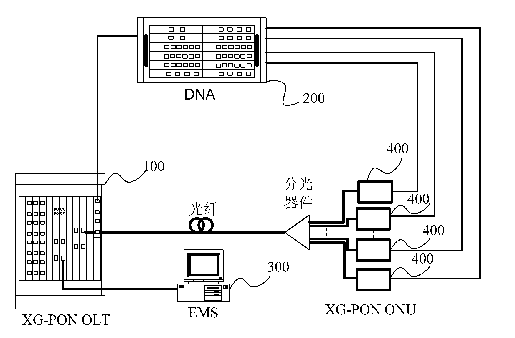
[0042] In the embodiment of the present invention, a DBA cycle is taken as an example to describe the flow of dynamic bandwidth allocation performed by the OLT in the passive optical network.

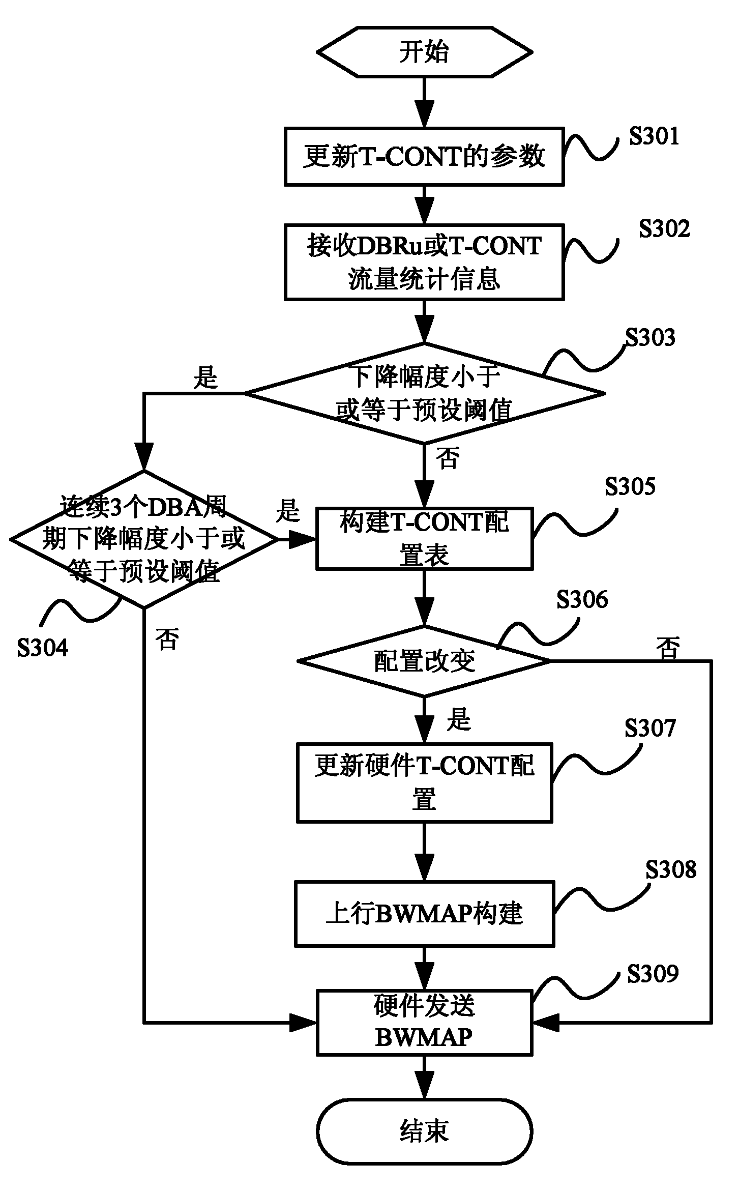
[0043] image 3 It is a flowchart according to an embodiment of the present invention, such as image 3 As shown, it mainly includes the following steps:

[0044] Step S301: When the current DBA cycle arrives, the OLT updates the parameters of the T-CONT according to the current user's SLA data, including: setting the T-CONT type, configuring the bandwidth value, etc.;

[0045] Step S302: The OLT outputs the bandwidth request of the T-CONT according to the DBRu information input by the ONU or the traffic statistics information of the T-CONT, and the bandwidth request carries the bandwidth required for the next stage of the T-CONT;

[0046] Among them, in the SR-DBA mode, the OLT calculates the bandwidth required for the next stage of the T-CONT according to the DBRu value reported by ...

Embodiment 2

[0056] The embodiment of the present invention explains the flow of the OLT constructing the T-CONT configuration table in Embodiment 1. In the embodiment of the present invention, the OLT needs to judge the type of the T-CONT during the process of constructing the T-CONT configuration table, such as TYPE 1 / 2, directly construct the T-CONT table and enter the hardware T-CONT configuration process; if it is TYPE3 / 4 / 5, further configuration of T-CONT is required, including priority (CLASS) and weight (WEIGHT ) configuration to further subdivide the bandwidth and further improve the bandwidth scheduling performance in the above-mentioned type of T-CONT.

[0057] Such as Figure 4 As shown, in Embodiment 2 of the present invention, the OLT constructs the T-CONT configuration table according to the following steps:

[0058] Step S401: The T-CONT configuration module of the OLT receives the uplink bandwidth request output by step S301 of Embodiment 1, and parses parameters such as ...

Embodiment 3

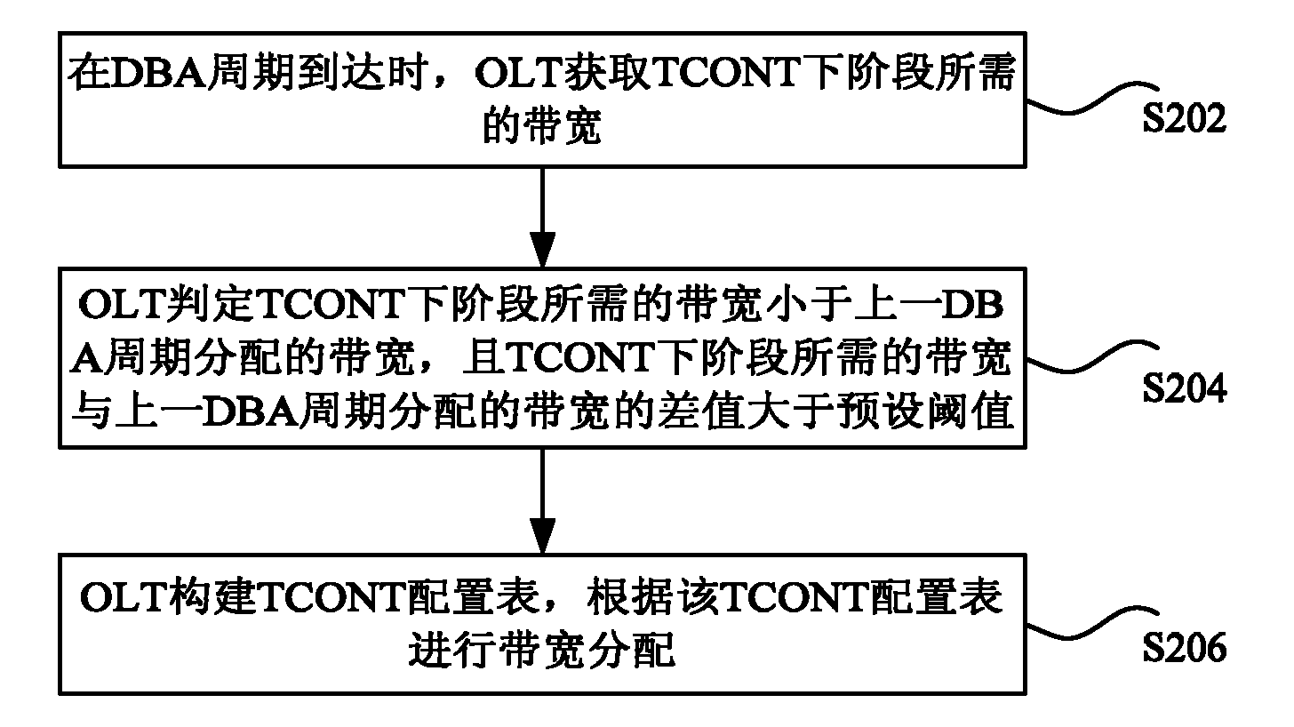
[0065] In the embodiment of the present invention, the DBA is in SR-DBA mode, and the bandwidth required by the OLT to obtain the next stage of the T-CONT is less than the bandwidth allocated in the previous DBA cycle, and the difference between the two is greater than the above-mentioned preset threshold, and the bandwidth of the T-CONT The type is Type1, combined with image 3 and Figure 4 , OLT realizes dynamic bandwidth allocation in the present embodiment and comprises the following steps:

[0066] Step S501: When the current DBA cycle arrives, the OLT updates the parameters of the T-CONT according to the current user's SLA data, including: setting the T-CONT type, configuring the bandwidth value, etc.;

[0067] Step S502: The OLT receives the DBRu information reported by the ONU, and outputs the bandwidth request of the T-CONT according to the DBRu information, and the bandwidth request carries the bandwidth required for the next stage of the T-CONT;

[0068] Step S50...


PUM


Abstract

The invention discloses a method and device for distributing the dynamic bandwidth of a passive optical network. The method comprises the steps that: an OLT (optical line terminal) obtains a bandwidth needed by a next stage of a T-CONT (transmission container) when a DBA (database administration) period reaches; the OLT judges that the needed bandwidth is less than the bandwidth distributed in the previous period and the difference between the needed bandwidth and the bandwidth distributed in the previous period is greater than a predetermined threshold; and the OLT builds a T-CONT configuration table, and the bandwidth distribution is performed according to the T-CONT configuration table. By the invention, the probability of packet loss can be reduced, and the quality of service (QoS) of operators is improved.

Description

technical field [0001] The present invention relates to the communication field, in particular to a dynamic bandwidth allocation method and device for a passive optical network. Background technique [0002] In the 10-Gigabit-capable Passive Optical Network (XG-PON operating network for short), common networking systems such as figure 1 As shown, the system consists of a network management server (EMS), an optical line terminal (Optical Line Terminal, referred to as OLT), an optical splitter (Optical Splitter) and several optical network units (Optical Network Unit, referred to as ONU) (the maximum number is 1024) and a data network analyzer (DataNetwork Analyzer, referred to as DNA), the transmission direction from the OLT to the ONU is the downstream direction (downstream), and the transmission direction from the ONU to the OLT is the upstream direction (upstream), thereby realizing data services and Configuration management and other functions. [0003] The XG-PON netwo...

Claims


Application Information

Patent Timeline
Patent Type & Authority Applications(China)
IPC IPC(8): H04L12/56H04Q11/00H04L47/76
CPCH04L47/762H04Q2011/0064H04Q11/0067
Inventor 黄健王康黄文杰
Owner ZTE CORP
Why Eureka
Try Eureka