
Continuous extruder

A technology of extruder and discharge area, which is applied in the field of continuous extruder, can solve the problems of long time consumption and uncontinuous process, and achieve the effect of improving electrical conductivity and mechanical properties, and suppressing phase separation

Active Publication Date: 2011-06-22
SHINIL CHEM IND CO LTD
View PDF6 Cites 1 Cited by
  • Summary
  • Abstract
  • Description
  • Claims
  • Application Information

AI Technical Summary

Problems solved by technology

Therefore, at least two extruders are required for melt-processing polymers, and the melting and mixing process and stirring process are performed separately, so that the process cannot be continuously performed, and has the disadvantage of taking too long

Method used


Image

  • Continuous extruder
  • Continuous extruder
  • Continuous extruder

Examples


no. 1 example

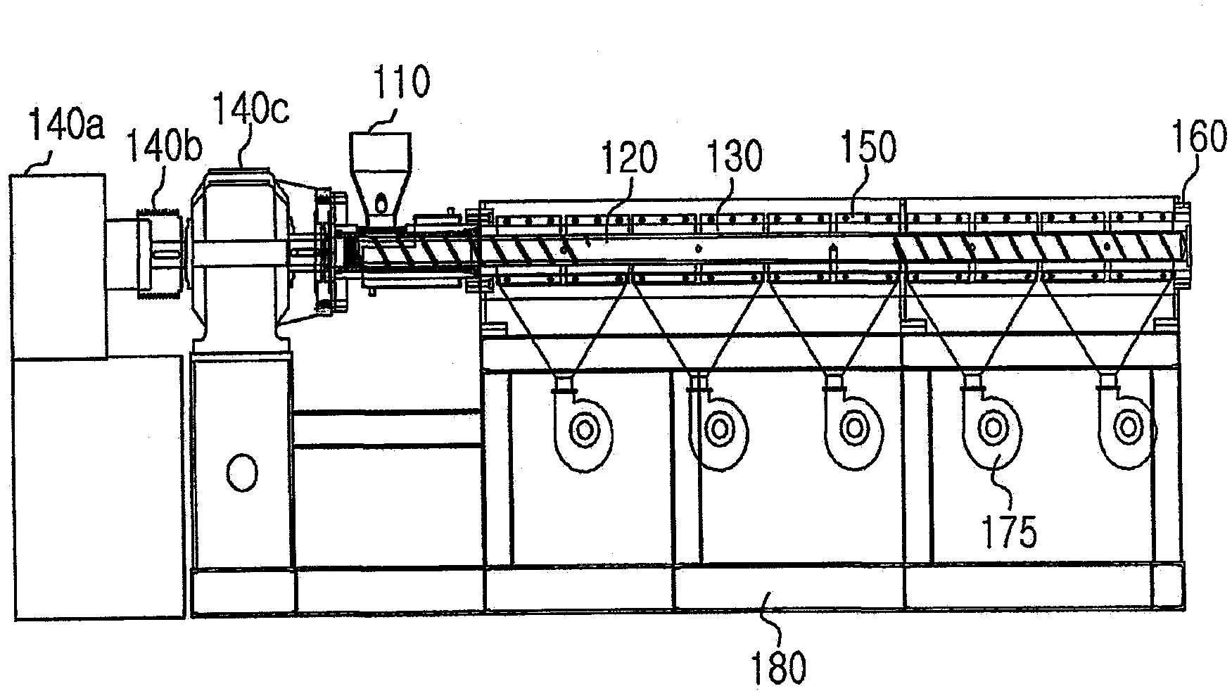
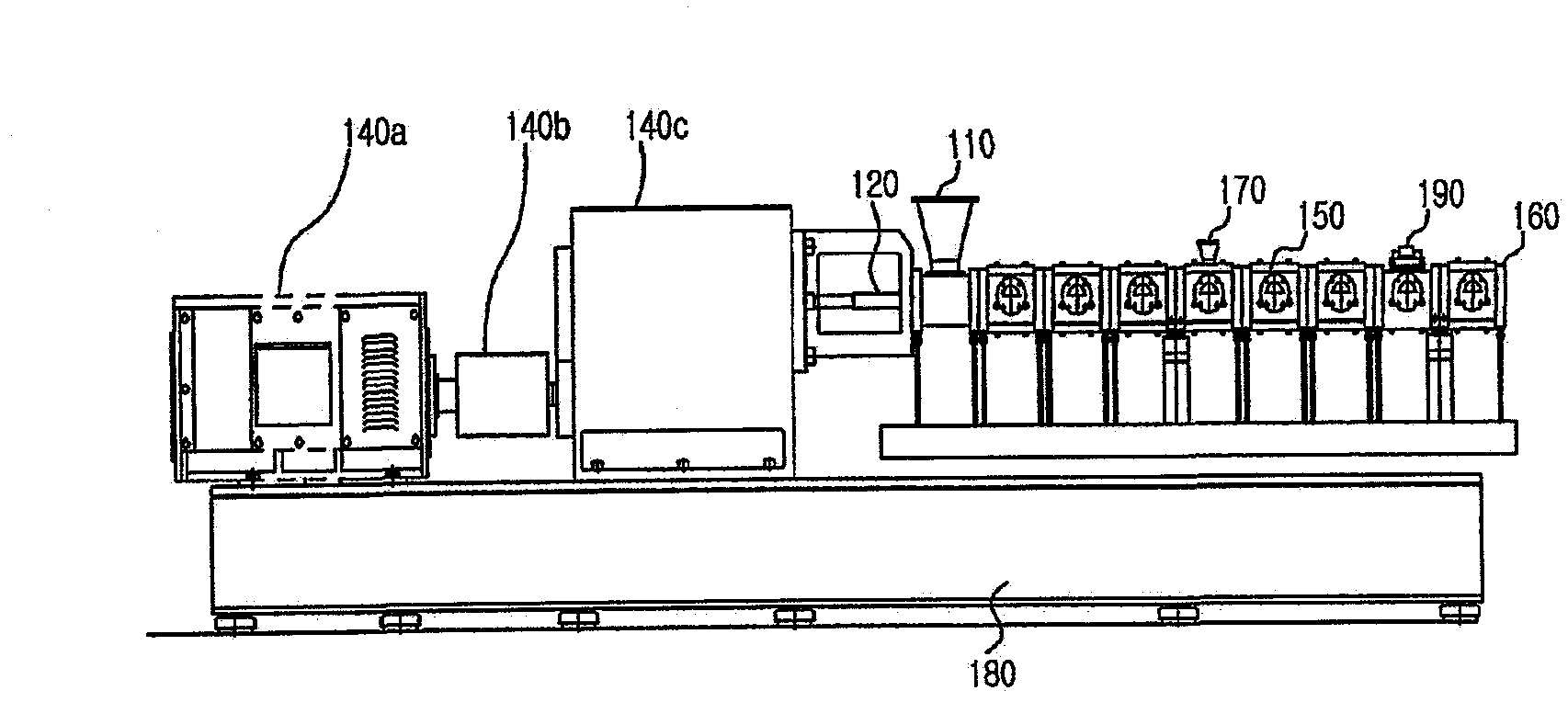
[0070] To the hopper 110 of the continuous twin-screw extruder, a mixture comprising an average particle size of 8 μm, 0-15% by weight of clay, and 85-100% by weight of polyamide resin was fed.

[0071] The polyamide resin and clay are stirred, melted and compressed in the melting and compression zone Z1 of the continuous twin-screw extruder. The temperature of the melting zone was maintained at 250°C by the heating unit. At this time, the two rotating shafts 120 driven by the motor rotate clockwise, the rotating speed of the rotating shafts 120 is 230rpm, and the wheelbase between the two rotating shafts is 5cm. The rotating shaft 120 in the melting and compressing zone Z1 is formed into a spiral screw shape in order to agitate and compress the raw material injected through the hopper 110 and supply it to the dispersing zone Z2. The helix angle of the helical screw is about 30°, the distance between the thread of the helical screw and the barrel 130 is 1 / 60 of the diameter o...

no. 2 example

[0076] 78.0 to 98.0% by weight of polyamide resin and 2.0% by weight of clay having an average particle size of 8 μm were charged into the hopper 110 of the continuous twin-screw extruder.

[0077] The polyamide resin and clay were stirred in the continuous twin-screw extruder, and melted and compressed at a temperature of 250° C. higher than the melting temperature of the polyamide resin.

[0078] After the polyamide resin and the clay are fed into the continuous twin-screw extruder and melted, the clay is peeled off to be dispersed in the composition of the polyamide resin process by side feeding ) way to put in glass fibers with a weight percentage of 0-25%.

[0079] The subsequent process is the same as the first embodiment except that the temperature of 240° C. is maintained in the dispersion zone Z2, so as to obtain a granular polyamide nanocomposite.

no. 3 example

[0081] 76.3-96.3% by weight of polyamide resin, 2.0% by weight of clay with an average particle size of 8 μm, and 1.7% by weight of carbon nanotubes were charged into the hopper 110 of the continuous twin-screw extruder.

[0082] The polyamide resin and clay were stirred in the continuous twin-screw extruder, and melted and compressed at a temperature of 250° C. higher than the melting temperature of the polyamide resin.

[0083] After the polyamide resin and the clay are fed into the continuous twin-screw extruder and melted, the clay is peeled off to be dispersed in the composition of the polyamide resin process by side feeding ) way into 0 to 20% by weight of glass fiber.

[0084] The subsequent process is the same as the first embodiment except that the temperature of 240° C. is maintained in the dispersion zone Z2, so as to obtain a granular polyamide nanocomposite.


PUM

PropertyMeasurementUnit
angleaaaaaaaaaa
angleaaaaaaaaaa
particle sizeaaaaaaaaaa

Abstract

The present invention relates to a continuous extruder including a melting and compression zone having a spiral screw-shaped shaft structure which melts and compresses thermoplastic polymer resin and additive material inputted through a hopper, and a dispersion section which moves the thermoplastic polymer resin and additive material to a discharge section while dispersing the additive material in the thermoplastic polymer resin by compressive and shear stress, and a discharge die which discharges the composition where the additive material is dispersed in the polyamide resin. The dispersion section has a shaft structure which at least comprises an upwardly tapered compression unit, and a front flat end unit which is straight and is formed adjacent to the upwardly tapered compression unit. In the dispersion section, the ratio of the length to the diameter of the shaft is within 20-60. According to the present invention, a separate extruder is not necessary and mixing, melting, compression, dispersion and discharging can be performed in situ. In addition, layered material like clay can be dispersed on the polymer resin by being efficiently delaminated thereon, without adding additives such as a surfactant, dispersing agent, antioxidant and coupling agent.

Description

technical field [0001] The present invention relates to a continuous extruder, in particular to an extruder that can stir, melt, compress, disperse and discharge in situ without special addition of extruder, and without adding surfactants, dispersants, antioxidants, A continuous extruder that effectively peels layered substances such as clay into resin polymers and disperses them as additives for coupling agents. Background technique [0002] For polymer composites, the required properties cannot be obtained from a single polymer, so other raw materials are mixed, melted and kneaded to produce polymer composites. [0003] However, in order to produce a polymer composition, it is necessary to go through a process of melting and kneading a thermoplastic resin, but there is a difference in melting temperature between the thermoplastic resin and other raw materials that need to be stirred, and it is difficult to control the viscosity and cause it to be melted The polarities and...

Claims


Application Information

Patent Timeline
Patent Type & Authority Applications(China)
IPC IPC(8): B29C47/36B29C48/67B29C48/07B29C48/395B29C48/40B29C48/54B29C48/55B29C48/57B29C48/63
CPCB29C47/0019B29C47/385B29C47/38B29C47/6031B29C47/6093B29C47/6037B29C47/60B29C47/6056B29C47/64B29C48/397B29C48/07B29C48/395B29C48/54B29C48/55B29C48/57B29C48/63B29C48/67B29C48/40B29C48/36B29C48/505
Inventor 徐今锡南炳旭曼沃尔·侯赛因梁金浩
Owner SHINIL CHEM IND CO LTD
Learn More