Control device for internal combustion engine

A technology for a control device and an internal combustion engine, which is applied to the control of coolant flow, the cooling of the engine, and the pressure of the lubricant, etc., can solve the problems of narrowing of the execution area, difficulty in suitable coordinated control, and inability to greatly improve the warm-up performance of the internal combustion engine, etc. To achieve the effect of improving preheating

Inactive Publication Date: 2011-06-22
TOYOTA JIDOSHA KK
View PDF2 Cites 5 Cited by
  • Summary
  • Abstract
  • Description
  • Claims
  • Application Information

AI Technical Summary

Problems solved by technology

However, the operation area where the cooling water circulation stop control is performed and the operation area where the low oil pressure control of the 2-stage hydraulic system is performed are largely overlapped.
Therefore, when the two controls are executed in combination, if the temperature of the internal combustion engine changes by executing either control, the other control may not be properly executed due to the influence.
For example, when the two-stage control is performed based on the cooling water temperature, when the circulation of the cooling water is stopped, the cooling water temperature rises rapidly, so the execution area of ​​the low oil pressure control by the two-stage hydraulic system is reduced
[0008] In this way, in the conventional technology, since it is difficult to appropriately coordinate and control the two systems, there is a problem that the warm-up performance of the internal combustion engine cannot be greatly improved.

Method used


Image

  • Control device for internal combustion engine
  • Control device for internal combustion engine
  • Control device for internal combustion engine

Examples


Embodiment

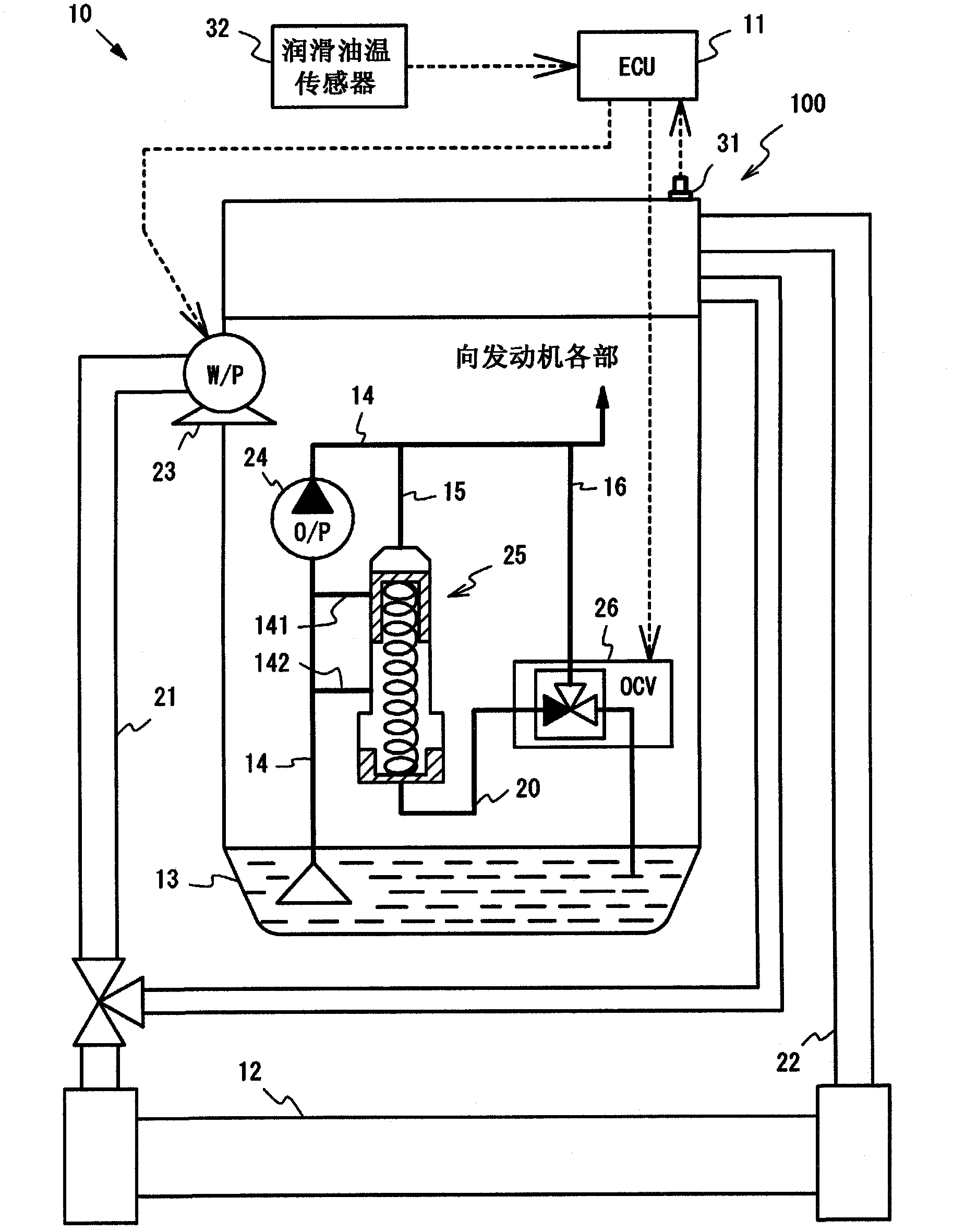
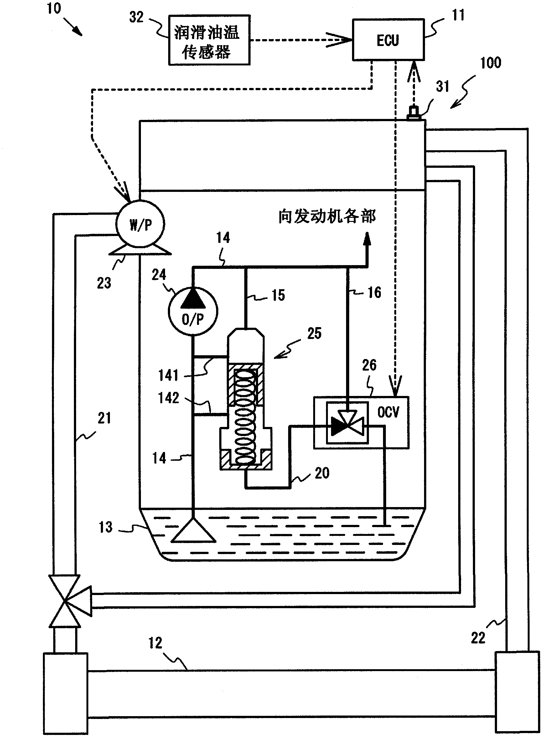
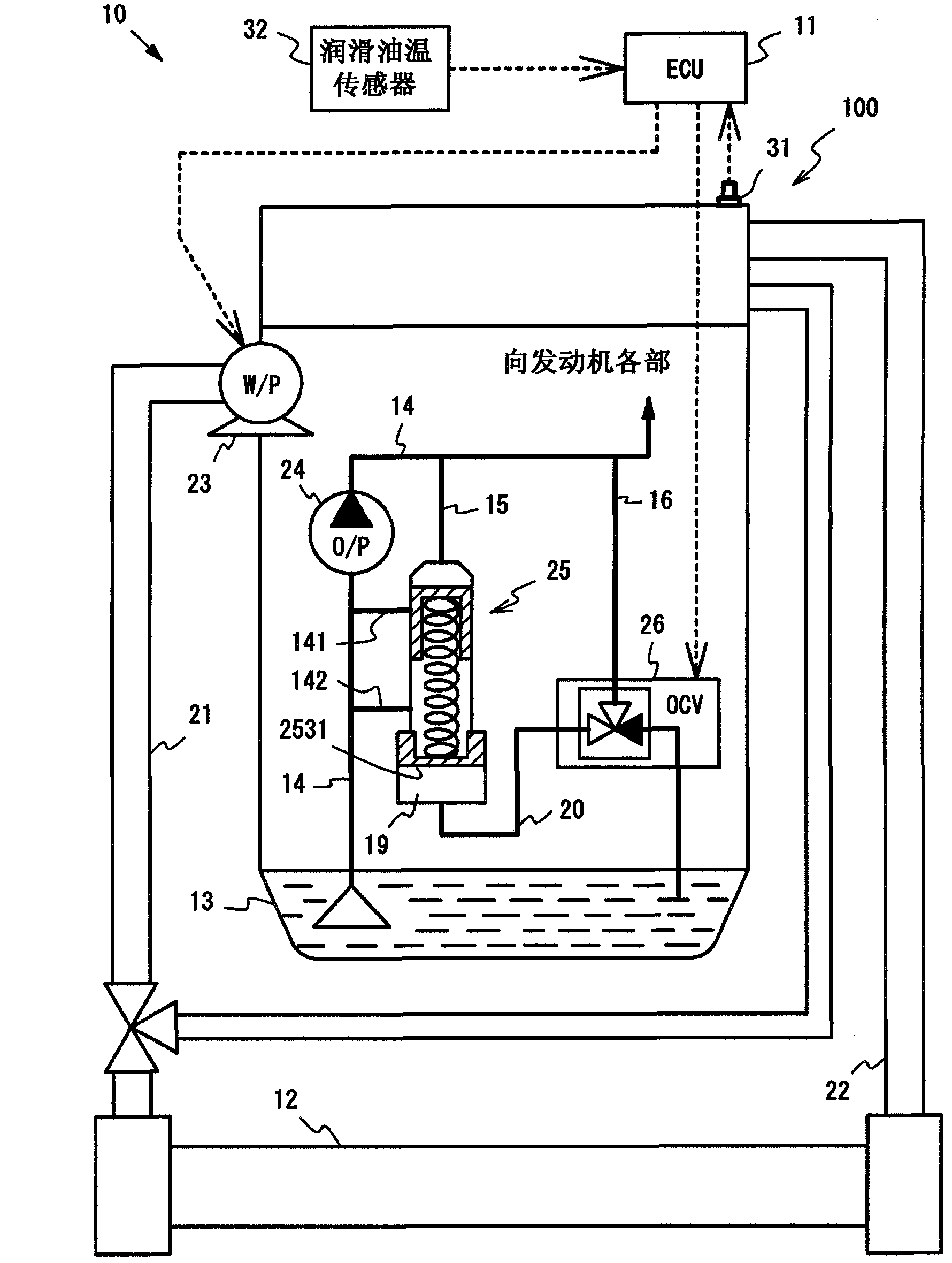
[0047] Figure 1~4 It is a configuration diagram showing a schematic configuration of a vehicle control system 10 incorporating a control device for an internal combustion engine according to the present invention. The vehicle control system 10 includes an engine 100 as a power source. In addition, the vehicle control system 10 includes an ECU (Electronic Control Unit: Electronic Control Unit) 11 that collectively controls the operation of the vehicle control system 10 . Further, the vehicle control system 10 includes a first flow path 21 and a second flow path 22 through which the refrigerant circulating between the radiator 12 and the engine 100 flows, and a water pump 23 that pressurizes and circulates the refrigerant. Further, the vehicle control system 10 includes an oil pump 24 for pressure-feeding and circulating lubricating oil, an oil overflow device 25 for adjusting the supply pressure of lubricating oil, and an oil control valve (hereinafter abbreviated as OCV) 26 ...


PUM


Abstract

A vehicle control system (10) is equipped with a water pump (23) that is equipped with an electromagnetic clutch, an oil relief device (25) and an OCV (26), a water temperature sensor (31), and an ECU (11). Based on the detection result of the water temperature sensor (31), the ECU (11) disengages the electromagnetic clutch of the water pump (23) and stops the circulation of cooling water, and instructs the OCV (26) to adjust the lubricating oil pressure to the low-pressure side by means of the oil relief device (25). Based on the detection result of the water temperature sensor (31) after the electromagnetic clutch of the water pump (23) has been engaged for a prescribed period of time, the ECU (11) determines whether to stop executing the adjustment of the lubricating oil pressure to the low-pressure side by means of the oil relief device (25).

Description

technical field [0001] The invention relates to a control device for an internal combustion engine. Background technique [0002] In recent years, in order to improve the warm-up performance of the internal combustion engine, control is performed to temporarily stop the circulation of cooling water by stopping the driving of the water pump during the warm-up operation of the water-cooled internal combustion engine. For example, a technique has been proposed in which, when the internal combustion engine is cold, an electric pump for pressure-feeding cooling water is intermittently operated to intermittently circulate the cooling water in the cooling water channel inside the internal combustion engine. According to this technology, it is possible to suppress a local temperature rise in the periphery of the cylinder and reduce the amount of heat radiation from the internal combustion engine, thereby facilitating warm-up of the internal combustion engine (see Patent Document 1)....

Claims


Application Information

Patent Timeline
Patent Type & Authority Applications(China)
IPC IPC(8): F01M1/16F01P7/16
CPCF01M1/16F01P7/162
Inventor 小林日出夫杉山敏久蚁泽克彦山田贤一林邦彦细井章仁菅本周作
Owner TOYOTA JIDOSHA KK
Why Eureka
Try Eureka