Mid-driving booster bicycle

A technology for power-assisted bicycles and bicycles, which is applied in the directions of rider drive, vehicle components, and vehicle gearboxes. Simple, motor-driven energy-saving effect

Inactive Publication Date: 2011-06-29
韩玉金
View PDF1 Cites 20 Cited by
  • Summary
  • Abstract
  • Description
  • Claims
  • Application Information

AI Technical Summary

Problems solved by technology

Although the mid-drive power-assisted bicycle is equipped with two sets of speed change systems of motor drive and human riding, its two chains act together on the rear wheel shaft, which makes the structure of the mid-drive power-assisted bicycle complicated, inconvenient for production, installation, and maintenance, which affects Beautiful and costly

Method used


Image

  • Mid-driving booster bicycle
  • Mid-driving booster bicycle
  • Mid-driving booster bicycle

Examples


Embodiment 1

[0035] Embodiment 1: Taking an electric power-assisted bicycle as an example, two clutch devices are arranged on the external output shaft of the motor driver and described.

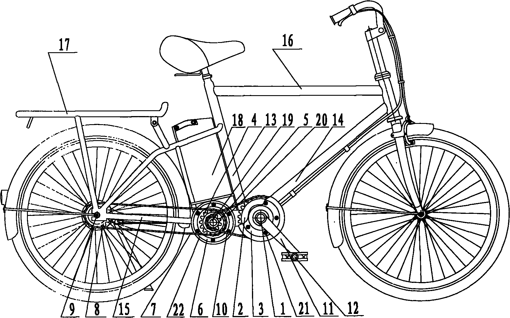
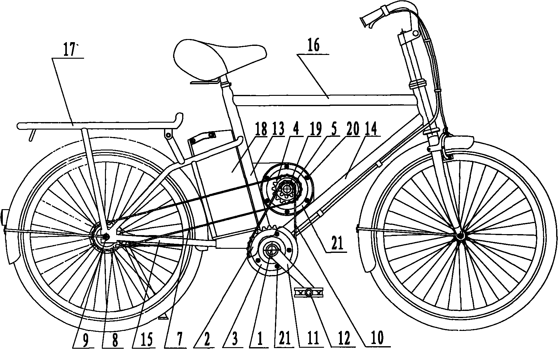
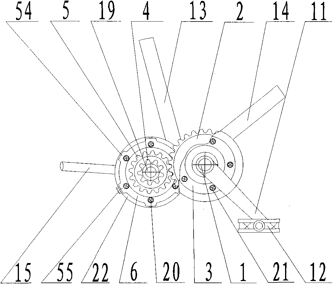
[0036] Such as figure 1 , Figure 4 , Figure 5 , Figure 11 , Figure 12 Shown: in the centrally driven power-assisted bicycle, its motor clutch device 33 and pedal clutch device 34 are integrated or combined as separate parts, and are all set and fixed on the power output shaft 19 outside the motor driver 6 and the motor clutch Device 33 and pedal clutch device 34 use ratchet mechanism (or flywheel structure) instead and make ratchet integrated two-way clutch, motor clutch device 33 can also be adopted roller (wedge) formula clutch device and pedal clutch device 34 adopts The ratchet type clutch device is combined into one body, and vice versa; wherein, the inner ring of the motor clutch device 33 is fixed on the power output shaft 19, and the output shaft 39 of the motor clutch device 33 is suppor...

Embodiment 2

[0045] Embodiment 2: Taking an electric power-assisted bicycle as an example, two clutch devices are arranged inside the motor driver and described.

[0046] Such as Figure 7 , Figure 13Shown: in the centrally driven power-assisted bicycle, its motor clutch device 33 and pedal clutch device 34 are integrated or combined as separate parts, and are all arranged in the inside of the motor driver 6 and connected with the speed changer. At this time, the motor clutch device The outer ring of the device 33 can be used in combination with the power output part 19' of the speed changer, and the transmission wheel 4 is retained on the output shaft 39 of the motor clutch device 33 by a lock nut 42 (or jumper), and the pedal transmission wheel 5. It is fixed on the transmission shaft 50 by the circlip 41 (or lock nut), and the other end of the transmission shaft 50 (or the outer ring of the motor clutch device 33) is supported by the bearing 36 on the output of the rotor pinion shaft ...

Embodiment 3

[0049] Embodiment 3: Taking an electric power-assisted bicycle as an example, a clutch device is arranged inside the motor driver and described.

[0050] Such as Figure 9 Shown: the centrally driven power-assisted bicycle, its motor clutch device 33 is arranged on the inside of the motor driver 6 and the power output part 19' of the speed changer is combined with the outer ring of the motor clutch device 33 for use, and the power output shaft 19 is clutched with the motor The inner ring of device 33 is combined into one and used, and the inner ring of pedal clutch device 34 and transmission wheel 4 are retained on the power output shaft 19 by jump spring 41 (or keyway, screw) (the inner ring of pedal clutch device 34 and transmission wheel 4 are retained on the power output shaft 19 Drive wheel 4 can be combined into one and used), pedal drive wheel 5 is fixed on the outer ring of pedal clutch device 34 by screw 40 (or the outer ring of pedal drive wheel 5 and pedal clutch de...


PUM


Abstract

The invention relates to a mid-driving booster bicycle. The booster bicycle comprises a bicycle body, a motor driver, an accumulator and a circuit controller, wherein the motor driver is arranged between a five-way pipe of a loop lug and a rear fork, above the five-way pipe of the loop lug or below the five-way pipe of the loop lug; a motor clutch device, a transmission wheel, a pedal clutch device and a pedal transmission wheel are fixedly connected to the power output shaft of the motor driver; the motor driver drives the transmission wheel to rotate through the output shaft of the motor clutch device; the pedal wheel drives the pedal transmission wheel through a chain so as to drive the transmission wheel to rotate through the pedal clutch device; the transmission wheel drives a gear shift mechanism on a rear axle through a chain to drive the mid-driving booster bicycle to run; and the motor clutch device and the pedal clutch device drive the motor and manually and synthetically or respectively drive the mid-driving booster bicycle to run according to different operation conditions. The mid-driving booster bicycle has the advantages of simple and light structure, comfortable manual driving, energy conservation of motor driving and wide application range, and can be widely applied in the fields of booster bicycles, booster tricycles, hybrid power booster vehicles, water boosters and the like.

Description

technical field [0001] The invention relates to a mid-drive power-assisted bicycle, in particular to a motor-driven power-assisted bicycle with double-chain drive for human riding power-assisted. Background technique [0002] As we all know, the mid-drive power-assisted bicycles sold on the market are all driven by a single chain, which is either large in size and heavy, inconvenient for production, installation and maintenance, or the number of teeth on the pedal sprocket does not match the number of teeth on the rear axle transmission mechanism. The number of teeth of the front drive sprocket is greater than the number of teeth of the gears of the rear wheel transmission mechanism, which will inevitably reduce the transmission torque of the system and consume energy for assisting the bicycle to start or climb; on the contrary, if the number of teeth of the front drive sprocket is smaller than that of the rear wheel It embodies the advantages of motor drive, but affects the...

Claims


Application Information

Patent Timeline
Patent Type & Authority Applications(China)
IPC IPC(8): B62M6/40B62M9/04B62M11/04
Inventor 韩玉金
Owner 韩玉金
Why Eureka
Try Eureka