Ultrasonic driving circuit and driving method and ultrasonic pulmonary function meter

A driving circuit and ultrasonic technology, which is applied in the field of ultrasonic, can solve the problems of inability to realize the portability of the ultrasonic spirometer and consume more energy, and achieve the effect of reducing volume, reducing energy consumption, and energy-saving drive

Pending Publication Date: 2019-08-27
广州畅呼医疗器械有限公司
View PDF0 Cites 1 Cited by
  • Summary
  • Abstract
  • Description
  • Claims
  • Application Information

AI Technical Summary

Problems solved by technology

[0005] However, when the current ultrasonic flow sensor is working, it needs to generate a continuous and fixed driving signal. This way of working requires more energy consumption. In this way, the ultrasonic flow sensor needs to work when it is connected to the mains, or it needs to be given to the ultrasonic The flow sensor wears a large battery device, which cannot achieve the portability of the ultrasound spirometer

Method used


Image

  • Ultrasonic driving circuit and driving method and ultrasonic pulmonary function meter
  • Ultrasonic driving circuit and driving method and ultrasonic pulmonary function meter
  • Ultrasonic driving circuit and driving method and ultrasonic pulmonary function meter

Examples


Embodiment 2

[0064] Such as Figure 6 As shown, the present embodiment provides an ultrasonic driving method, comprising the following steps:

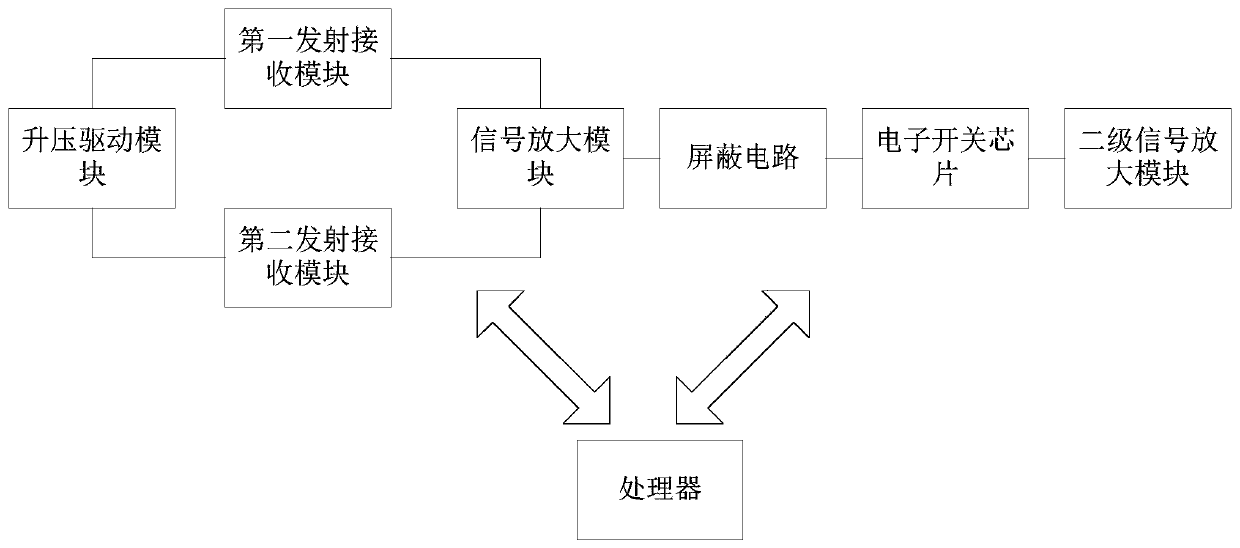
[0065] S1. Stepping up the voltage provided by the power module to a driving voltage;

[0066] S2. Using the driving voltage in turn to drive the first transmitting and receiving module and the second transmitting and receiving module to transmit ultrasonic signals according to the preset method, so that the first transmitting and receiving module and the second transmitting and receiving module receive the ultrasonic signals transmitted by each other;

[0067] S3. Convert the collected ultrasonic signal into an electrical signal, amplify the electrical signal and transmit it to the processor.

[0068] As a further preferred embodiment, it also includes steps S4-S5:

[0069] S4. Calculate the time difference of the ultrasonic wave between the first transmitting and receiving module and the second transmitting and receiving module according to the...

Embodiment 3

[0092] This embodiment provides an ultrasonic spirometer, including an insufflation tube and an ultrasonic driving circuit, and the ultrasonic driving circuit adopts the ultrasonic driving circuit described in Embodiment 1.

[0093] This embodiment has a one-to-one correspondence with the first embodiment, so it has the functions and beneficial effects corresponding to the first embodiment.

[0094] As a further preferred embodiment, it also includes a wireless communication module, and the wireless communication module is connected with the ultrasonic driving circuit.

[0095] The ultrasound spirometer is connected to the smart terminal through the wireless communication module, so that users can view the test results of the ultrasound spirometer with the help of the display screen of the smart terminal, without installing a display screen on the ultrasound spirometer, which greatly reduces the cost of ultrasonic testing. The volume of the spirometer.


PUM


Abstract

The invention discloses an ultrasonic driving circuit and driving method and an ultrasonic pulmonary function meter. The driving circuit comprises a processor, a boost driving module, a first transmitting and receiving module, a second transmitting and receiving module, a signal amplifying module and a power module supplying power to various modules, wherein the processor is separately connected with the boost driving module, the first transmitting and receiving module, the second transmitting and receiving module and the signal amplifying module; the boost driving module is separately connected with the first transmitting and receiving module and the second transmitting and receiving module; the signal amplifying module is separately connected with the first transmitting and receiving module and the second transmitting and receiving module. According to the ultrasonic driving circuit, voltage provided by the power module is boosted to driving voltage, and the driving voltage is adopted to drive the first transmitting and receiving module and the second transmitting and receiving module to transmit ultrasonic waves, thereby greatly reducing the energy consumption of the driving circuit; meanwhile, the battery volume can be reduced, thereby reducing the volume of equipment; the driving circuit can be widely used in the technical field of ultrasonic waves.

Description

technical field [0001] The invention relates to the field of ultrasonic technology, in particular to an ultrasonic driving circuit, a driving method and an ultrasonic pulmonary function instrument. Background technique [0002] With the development of the economy, the environmental pollution has become more and more serious, causing more and more people to suffer from respiratory diseases. Pulmonary function test is one of the necessary examinations for respiratory diseases. The purpose of detecting abnormalities in the respiratory system is to measure lung function through a spirometer. It has important guiding significance for early detection of lung and respiratory diseases, such as chronic bronchitis, emphysema, bronchial asthma, and intermittent lung disease. [0003] The core technology of spirometer is sensor technology, with emphasis on flow sensor. Most spirometer flow measurements are now made with turbine or differential pressure sensors. The principle of the t...

Claims


Application Information

Patent Timeline
IPC IPC(8): A61B8/00
CPCA61B8/00
Inventor 李坤耀周玉民田禾燊邓英强陈建民
Owner 广州畅呼医疗器械有限公司
Why Eureka
Try Eureka