Concrete pumping equipment and arm support state control system thereof

A state control and concrete pump technology, applied in the direction of mechanical equipment, electrical program control, pumps, etc., can solve problems affecting construction efficiency, material supply impact, vibration amplitude increase, etc., to improve convenience and construction efficiency, and avoid control errors , the effect of prolonging the service life

Active Publication Date: 2011-06-29
SANY AUTOMOBILE MFG CO LTD
View PDF6 Cites 62 Cited by
  • Summary
  • Abstract
  • Description
  • Claims
  • Application Information

AI Technical Summary

Problems solved by technology

[0005] Since the pumping method of the concrete delivery pump is a double-piston feeding cylinder, there is a reversing time during the working process, so that the concrete delivery is not carried out continuously, but in a pulsed manner, which is inevitable. The ground will produce material supply impact. Under the action of pulsating impact, the boom of the placing boom will vibrate, especially when the conveying volume of concrete is large or the frequency of pulsating impact is close to the natural frequency of the boom. It will be more violent, and the vibration amplitude will also increase significantly, which not only makes it difficult to control the position of the discharge port of the conveying pipeline, but also causes cracking of the boom, and even causes personal injury to the construction personnel; in order to prevent the above In the actual operation process, the staff had to reduce the pumping volume of the concrete delivery pump, however, this would affect the construction efficiency

Method used


Image

  • Concrete pumping equipment and arm support state control system thereof
  • Concrete pumping equipment and arm support state control system thereof
  • Concrete pumping equipment and arm support state control system thereof

Examples


Embodiment Construction

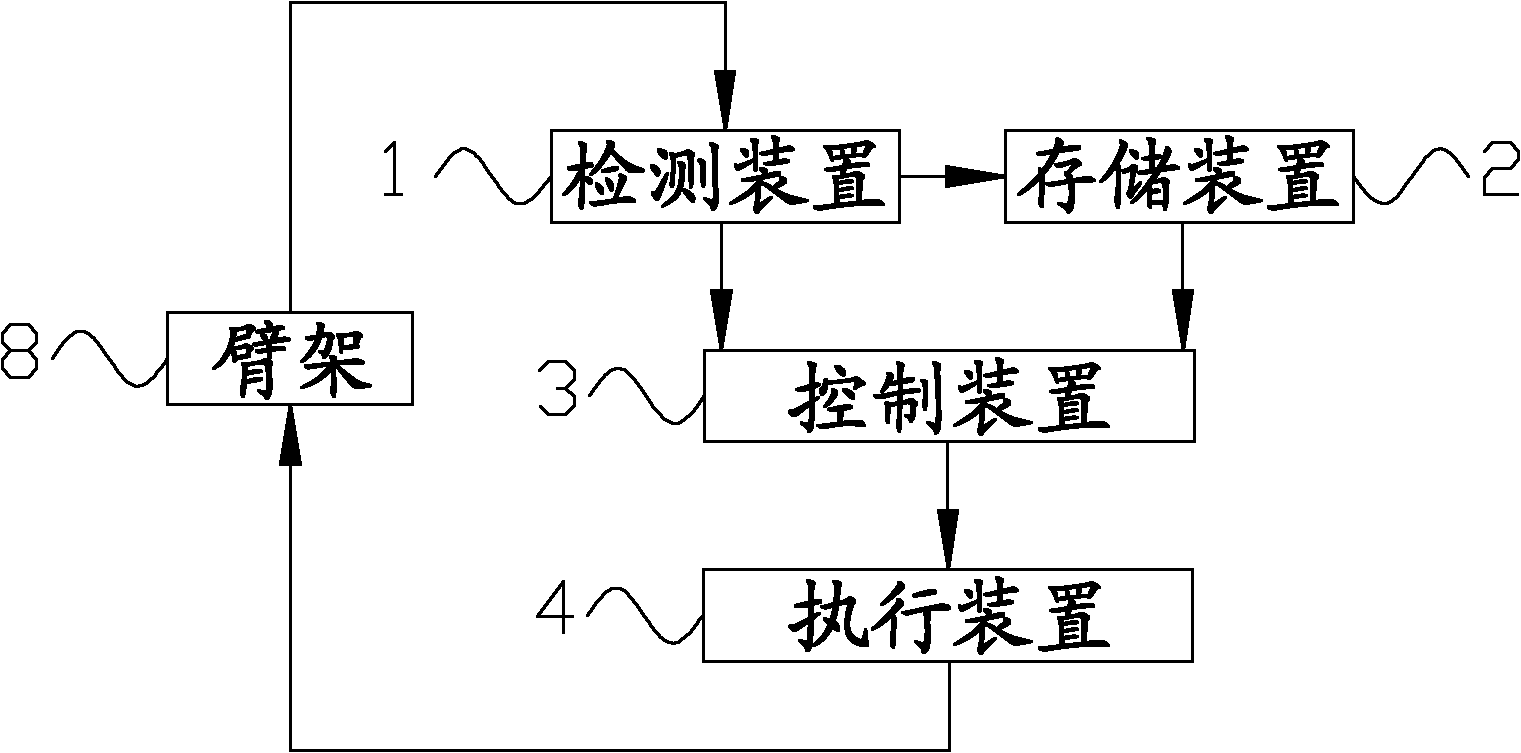
[0031] The core of the present invention is to provide a boom state control system, which can reduce the vibration of the boom boom on the basis of ensuring construction efficiency, and can avoid problems caused by the detection process of the detection device and the execution device. The control error caused by the time lag phenomenon in the action process can achieve timely vibration reduction, which improves the convenience of boom operation and construction efficiency, and prolongs the service life of the boom. Another core of the present invention is to provide a concrete pumping equipment including the above boom state control system.

[0032] In order to enable those skilled in the art to better understand the solution of the present invention, the present invention will be further described in detail below in conjunction with the accompanying drawings and specific embodiments.

[0033] Please refer to figure 1 , figure 1 It is a structural block diagram of the boom ...


PUM


Abstract

The invention discloses an arm support state control system, which comprises a detection device (1), a storage device (2), a control device (3) and an actuating device (4), wherein the detection device (1) is used for detecting the position state and vibration state of an arm support (8) of concrete pumping equipment to obtain a position state signal and a vibration signal; the storage device (2) is used for storing the vibration signal to obtain the periodical vibration signal of the arm support (8); the control device (3) is used for receiving the position state signal, the vibration signal and the periodical vibration signal and obtaining a control instruction according to a preset arm support vibration range, a preset advanced regulation time and a preset control policy; and the actuating device (4) is used for changing the state according to the control instruction and controlling the arm support (8) to act the preset arm support vibration range. The arm support state control system provided by the invention can avoid control error caused by time delay in the detection process of the detection device and the actuating process of the actuating device, absorb vibration in time and improve the operation convenience of the arm support. The invention also discloses concrete pumping equipment.

Description

technical field [0001] The invention relates to the field of concrete pumping equipment, in particular to a boom state control system. The present invention also relates to a concrete pumping equipment comprising the above-mentioned boom state control system and a boom state control method. Background technique [0002] With the rapid development of the national economy and urban construction, concrete pumping equipment, as the main construction machinery in the construction process, plays an increasingly important role. [0003] In order to accurately pump the concrete to the target position, a boom is generally installed on the concrete pumping equipment. In the prior art, there are two main types of settings for the boom: one is to install the boom and the concrete delivery pump together On the truck chassis, which is commonly referred to as a concrete pump truck; the other is to install the placing boom on the lifting table, crane or the wall column of the building. ...

Claims


Application Information

Patent Timeline
Patent Type & Authority Applications(China)
IPC IPC(8): E04G21/04G05B19/02
CPCE04G21/0454F04B15/02
Inventor 易小刚吴名陵胡栋华
Owner SANY AUTOMOBILE MFG CO LTD
Why Eureka
Try Eureka