Non-contact electromagnetic loading device for high speed electric spindle

A high-speed motorized spindle and loading device technology, applied in the testing of measuring devices, instruments, and mechanical components, can solve the problem of difficult loading of high-speed motorized spindles, and achieve the effects of significant economic benefits, low cost and high reliability.

Inactive Publication Date: 2011-06-29
XIAN UNIV OF TECH
View PDF4 Cites 35 Cited by
  • Summary
  • Abstract
  • Description
  • Claims
  • Application Information

AI Technical Summary

Problems solved by technology

[0003] The purpose of the present invention is to provide a non-contact electromagnetic loading device for high-speed electric spindles, which solves the problem of difficult loading of high-speed electric spindles in the prior art

Method used


Image

  • Non-contact electromagnetic loading device for high speed electric spindle
  • Non-contact electromagnetic loading device for high speed electric spindle
  • Non-contact electromagnetic loading device for high speed electric spindle

Examples


Embodiment Construction

[0014] The present invention will be described in detail below with reference to the drawings and specific embodiments.

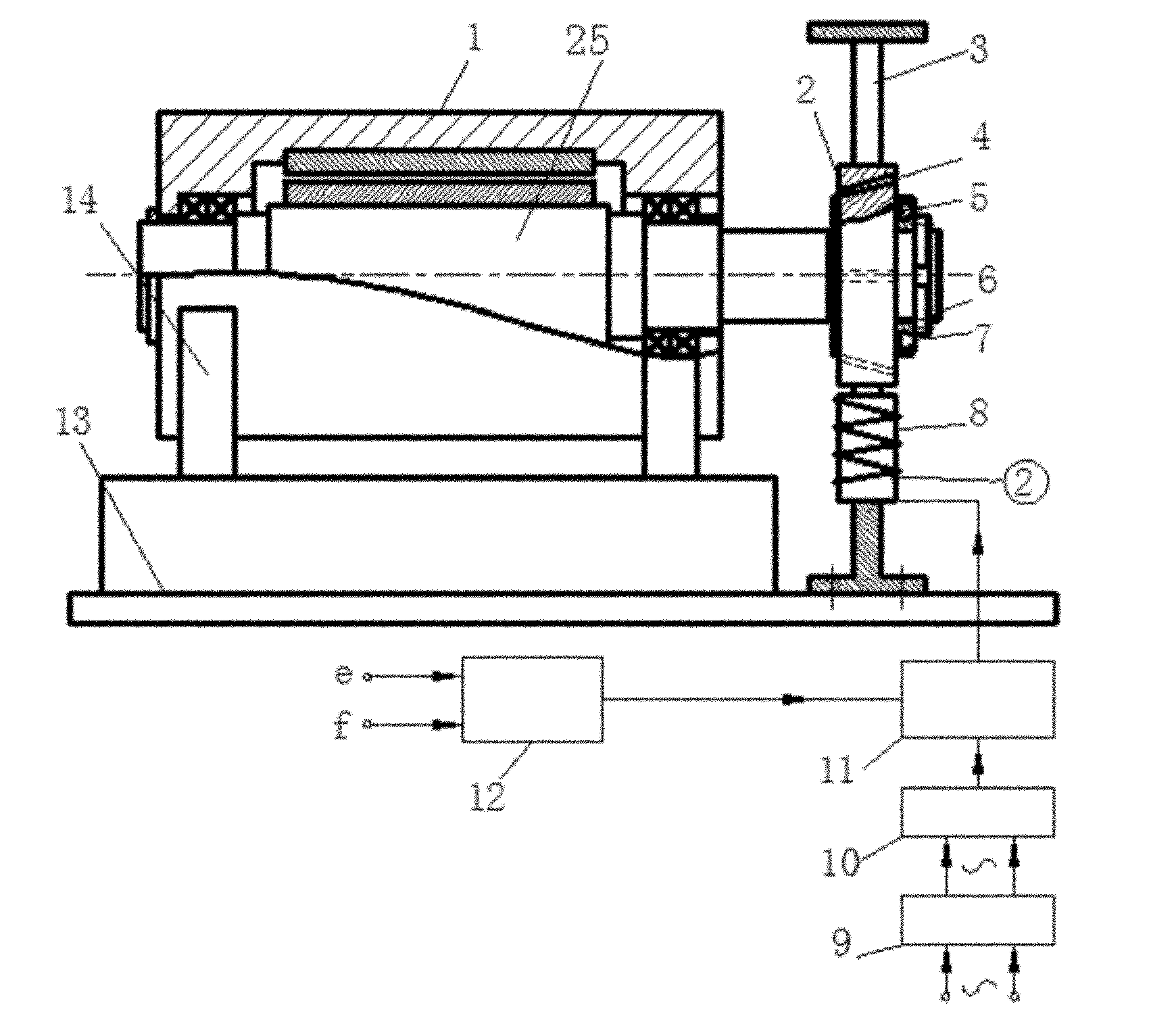
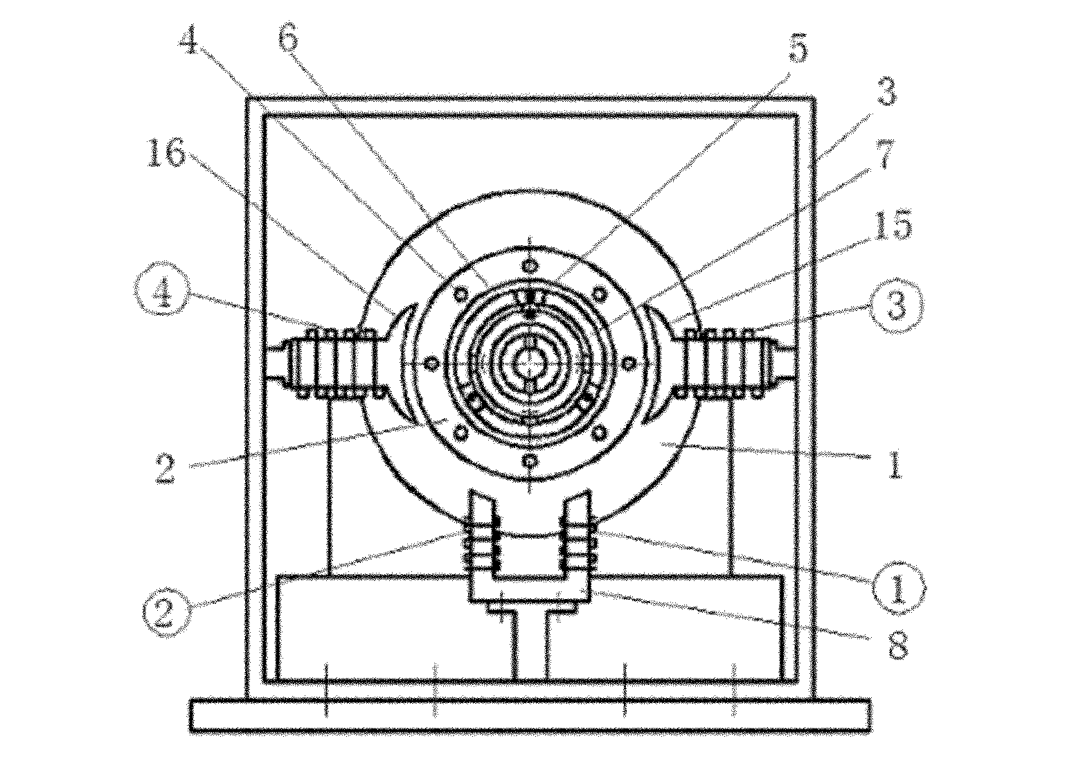
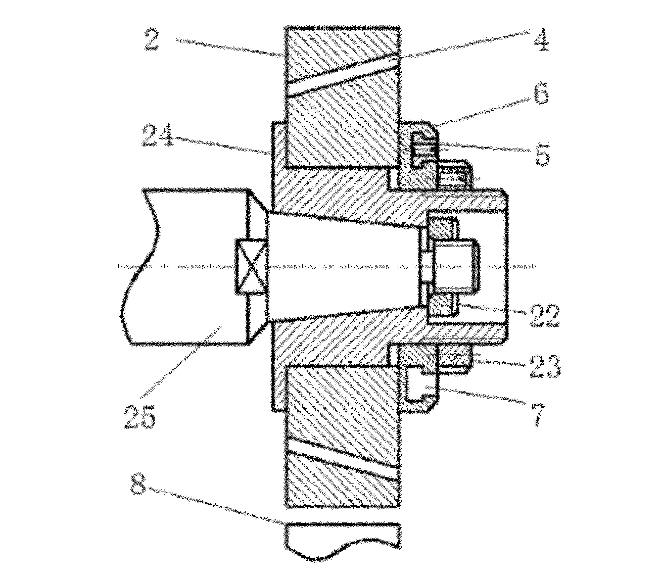
[0015] Such as figure 1 , figure 2 , image 3 The structure of the mechanical part of the device of the present invention is that a support 14 and an integral support 3 are provided on the worktable 13. The support 14 is fixed with an electric spindle 1, and the axis of the electric spindle 1 is covered with a mandrel 25, a mandrel 25 A flange 24 is coaxially connected to one end of the electric spindle 1, and the flange 24 is fixedly connected to the mandrel 25 through a lock nut 22. The flange 24 is sleeved with a loading disc 2, and the loading disc 2 and the integral support 3 are located In the same vertical plane, the outer end of the loading disc 2 is provided with a balance disc 6, and the balance disc 6 is provided with a plurality of balance weights 5 in the T-shaped groove 7 opened along the circumference, and the outer end of the balance disc 6 is ...


PUM


Abstract

The invention discloses a non-contact electromagnetic loading device for a high speed electric spindle, wherein the mechanical part of the device is as follows: an electric spindle is fixed on a supporting seat; a central spindle is sleeved in the inner cavity of the electric spindle; one end of the central spindle is coaxially sleeved with a circular loading disc; a balancing device is arranged at the outer end of the circular loading disc; the circular loading disc is provided with an inclined through hole along the axial direction; an integral bracket is arranged around the circular loading disc; a radial force loading electromagnet is arranged on the lower part of the integral bracket and wrapped with direct current excitation coils (1) and (2); a left torque loading electromagnet and a right torque loading electromagnet are respectively arranged on two sides of the integral bracket; each of the left and right torque loading electromagnets is wrapped with the direct current excitation coils (3) and (4); the electric part of the device comprises a PWM (pulse width modulation) switch power amplifier; the output end of the PWM switch power amplifier is simultaneously connected with a magnetic field controller and the direct current excitation coils (1), (2), (3) and (4) while the input end of the PWM switch power amplifier is orderly connected with a diode rectification circuit and a rectifier transformer; and the magnetic field controller is connected with an industrial control machine. The device provided by the invention solves th difficult loading problem in the performance analysis test of the high speed electric spindle.

Description

Technical field [0001] The invention belongs to the technical field of power control equipment and relates to a high-speed electric spindle non-contact electromagnetic loading device. Background technique [0002] As an emerging technology, high-speed electric spindles have been widely used in the manufacturing industry to realize high-speed and high-precision machining on CNC machine tools. In order to improve the machining accuracy and reliability of high-speed CNC machine tools, it is necessary to conduct experimental research on the reliability and dynamic performance of high-speed electric spindles under load. The test must first solve the loading problem of high-speed electric spindles. At present, there are few researches on the loading problem of high-speed electric spindle test at home and abroad. The proposed loading method is still the drag-type loading used in low-speed motor loading, that is, the dynamometer as the loading device is coaxially connected with the motor...

Claims


Application Information

Patent Timeline
Patent Type & Authority Applications(China)
IPC IPC(8): G01M13/00
Inventor 刘宏昭邱荣华周训通原大宁何强
Owner XIAN UNIV OF TECH
Why Eureka
Try Eureka