Orientation layer and preparation method thereof, and liquid crystal display device comprising orientation layer
A technology of orientation layer and orientation groove, which is applied in nonlinear optics, instruments, optics, etc., can solve the problems of poor uniformity of orientation groove and occurrence of debris, achieve uniform distribution, avoid friction debris, and improve production efficiency
- Summary
- Abstract
- Description
- Claims
- Application Information
AI Technical Summary
Problems solved by technology
Method used
Image

Examples
Embodiment 1
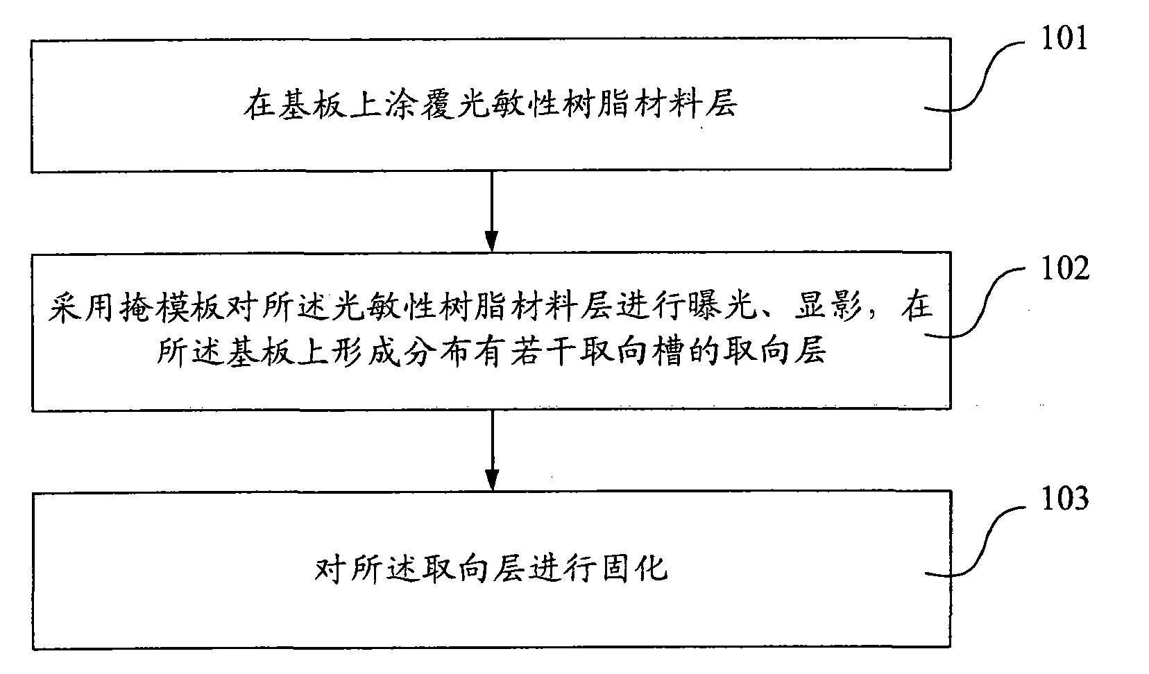
[0039] The embodiment of the present invention provides a method for preparing an alignment layer. The preparation method is different from the conventional rubbing method, and the alignment layer is prepared by exposing and developing a mask. figure 1 It is a schematic flow diagram of Embodiment 1 of the preparation method of the alignment layer of the present invention, as figure 1 As shown, the preparation method of the alignment layer of this embodiment may include the following three steps:
[0040] Step 101, coating a photosensitive resin material layer on the substrate.
[0041] First, a layer of photosensitive resin material is coated on the array substrate or the color filter substrate. The material can be other photosensitive materials.
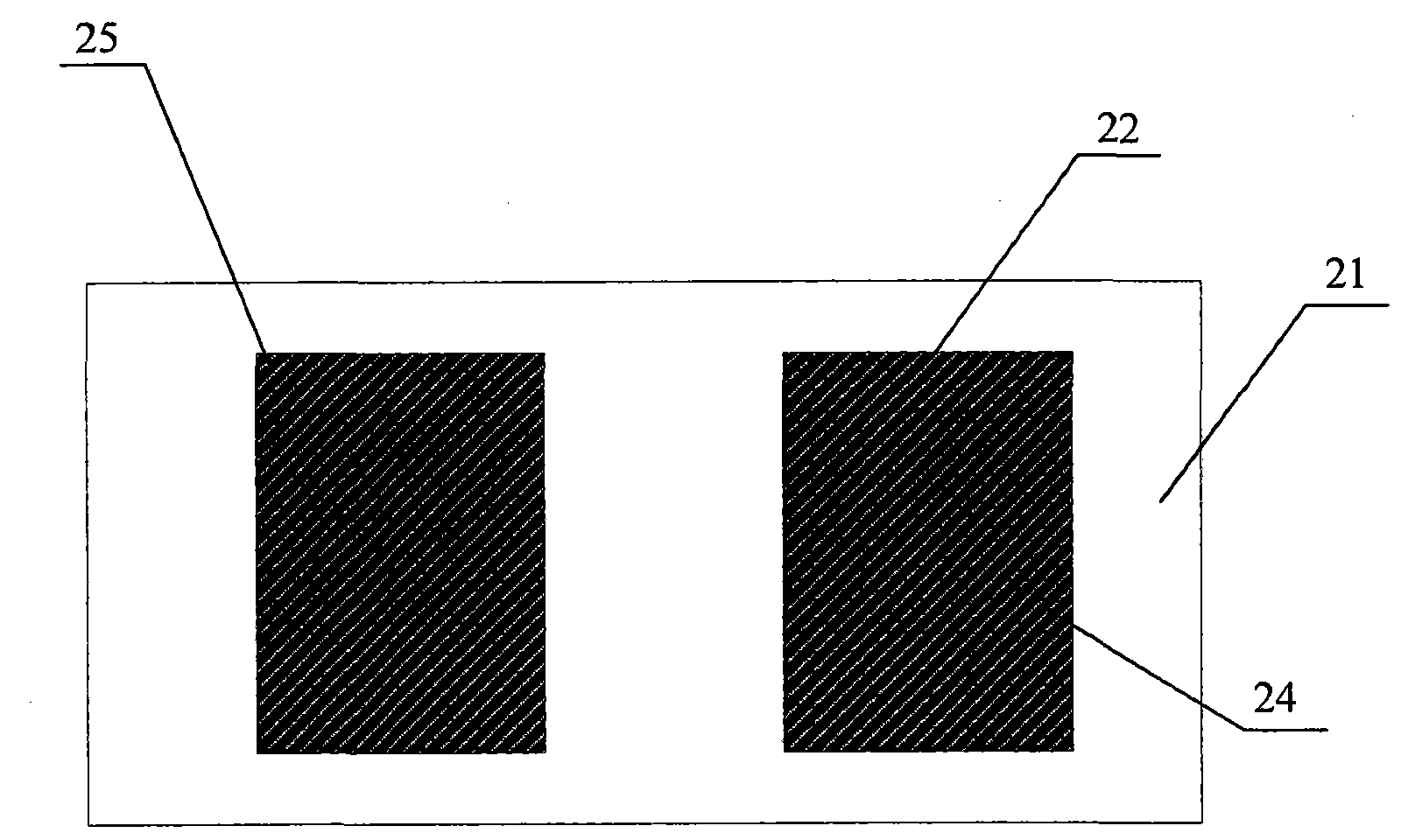
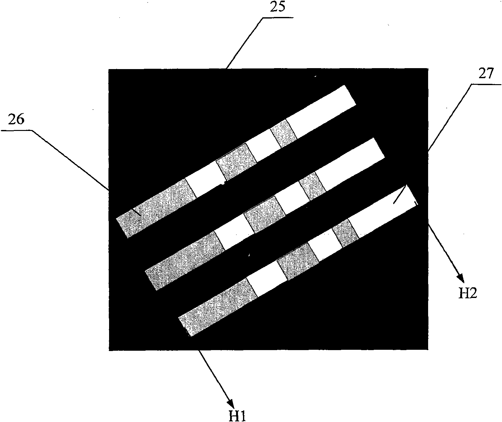
[0042] Step 102 , using a mask to expose and develop the photosensitive resin material layer to form an alignment layer distributed with several alignment grooves on the substrate.
[0043] Step 103, curing the alignment layer. ...
Embodiment 2
[0054] Figure 8 It is a schematic flow chart of Embodiment 2 of the preparation method of the alignment layer of the present invention. The main difference between the preparation method of this embodiment and Embodiment 1 is that the photosensitive resin material coated on the substrate is assumed to be a polyimide-based photosensitive resin. The photosensitive resin material is usually yellow, and the prepared alignment layer is required to be transparent, so it is necessary to perform a destaining process on the polyimide-based photosensitive resin material. Specifically, the preparation method of this embodiment may include the following steps:
[0055] Step 201, coating a photosensitive resin material layer on the substrate.
[0056] First, a layer of polyimide-based photosensitive resin material layer is coated on the array substrate or the color filter substrate.
[0057] Step 202 , using a mask to expose and develop the photosensitive resin material layer to form an...
Embodiment 3
[0063] The embodiment of the present invention also provides an alignment layer prepared by the above alignment layer preparation method. The difference between the alignment layer and the existing alignment layer is that its material is a photosensitive resin material, that is, the material of the alignment layer in this embodiment has photosensitive sex. For example, it may be a polyimide-based photosensitive resin material. And the orientation layer is distributed with a number of orientation grooves which are more evenly distributed than the existing structure.
[0064] The alignment layer of this embodiment can significantly improve the display quality of the LCD panel due to its more uniform appearance and no defects such as debris.
PUM
 Abstract
Description
Claims
Application Information
 - Generate Ideas
- Intellectual Property
- Life Sciences
- Materials
- Tech Scout
- Unparalleled Data Quality
- Higher Quality Content
- 60% Fewer Hallucinations
Browse by: Latest US Patents, China's latest patents, Technical Efficacy Thesaurus, Application Domain, Technology Topic, Popular Technical Reports.
© 2025 PatSnap. All rights reserved.Legal|Privacy policy|Modern Slavery Act Transparency Statement|Sitemap|About US| Contact US: help@patsnap.com