Beam-forming method for forming array antenna of variable beam

A beamforming method and array antenna technology, applied in the direction of antennas, electrical components, etc., can solve problems such as difficult to achieve model forming and variable beams, and achieve the effects of optimized radiation efficiency, wide application range, and simple engineering implementation

Active Publication Date: 2011-06-29
XIAN INSTITUE OF SPACE RADIO TECH
View PDF4 Cites 28 Cited by
  • Summary
  • Abstract
  • Description
  • Claims
  • Application Information

AI Technical Summary

Problems solved by technology

[0005] To sum up, the traditional array antenna can form a fixed shaped beam, or form a fixed

Method used


Image

  • Beam-forming method for forming array antenna of variable beam
  • Beam-forming method for forming array antenna of variable beam
  • Beam-forming method for forming array antenna of variable beam

Examples


Example Embodiment

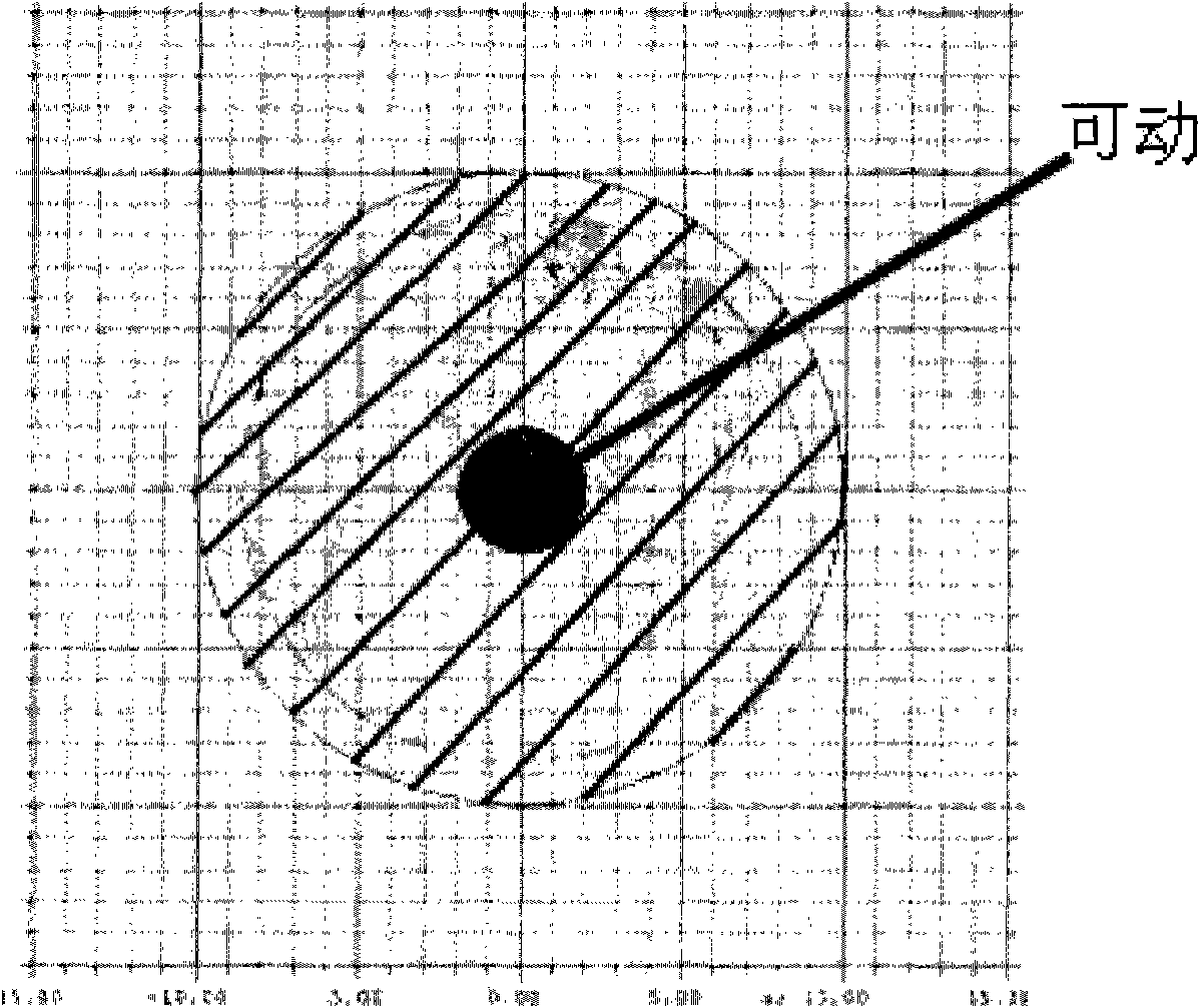
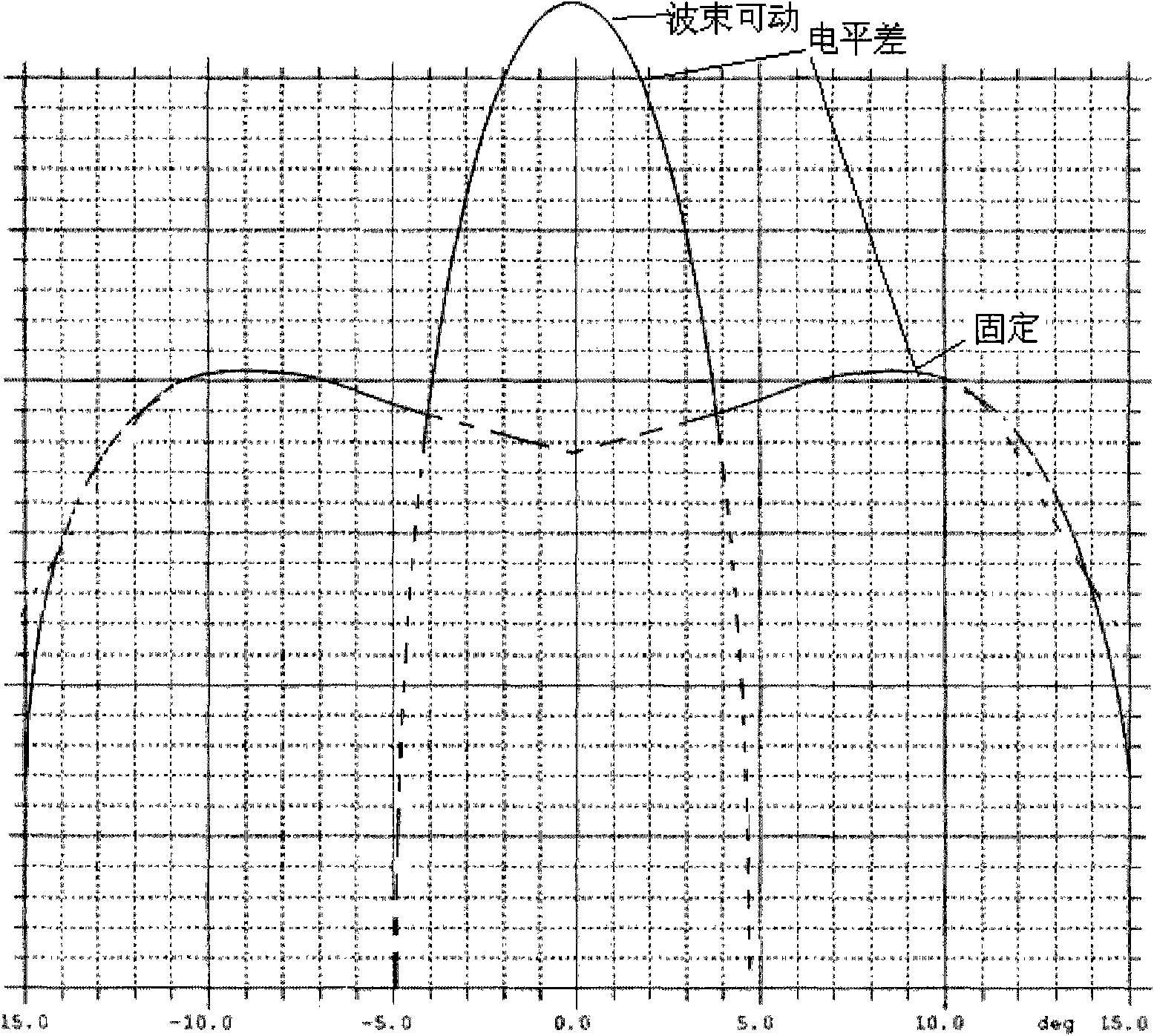
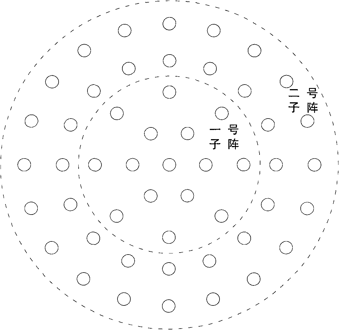
[0024] The implementation process of the present invention will be described in detail below in conjunction with specific embodiments. As attached image 3 As shown, the present invention designs a shaped variable beam array antenna composed of 51 elements, and the target beam is as figure 1 , 2 As shown, the pattern can be decomposed into a fixed shaped beam and a movable beam. Therefore, in the embodiment, the array unit is divided into two sub-arrays, the amplitude and phase of the two sub-arrays are optimized, and finally the sub-array pattern synthesis is performed.

[0025] The design steps are as Image 6 Shown:

[0026] 1) Divide the target beam into fixed beams and movable beams, and then divide all array elements in the array into n sub-arrays according to the total number of fixed beams and movable beams; in general, let the number of fixed beams be 1, so n is the number of movable beams+1;

[0027] As attached image 3 Shown is an embodiment of a shaped variable beam ar...


PUM


Abstract

The invention discloses a beam-forming method for forming an array antenna of a variable beam, which comprises the following steps of: (1) dividing a target beam into fixed beams and movable beams in shape according to the requirement of the target beam; (2) dividing all array elements of an array into n sub-arrays according to the number of the fixed beams and the number of the movable beams; (3) obtaining gain directional diagrams to be implemented by the sub-arrays by optimizing the layout of the sub-arrays and all unit amplitude phases in the sub-arrays under the environment of the whole arrays; (4) calculating phase directional diagrams of the respective sub-arrays, namely functions of phases varying along an angle of pitch Theta and an azimuth angle, under the environment of the whole arrays, and normalizing the phase directional diagrams of the respective sub-arrays to make the respective sub-arrays same-phase in pointing angles of the movable beams; and (5) determining weights of the respective sub-arrays according to a gain value of the target beam and the gain values of the respective sub-arrays obtained in the step (3), performing linear synthesis on the gain directional diagrams of the all sub-arrays by using the weights, and adjusting the weights of the respective sub-arrays to achieve an effect of forming as required.

Description

technical field [0001] The invention belongs to the field of microwave communication, and relates to a shaped variable beam array antenna, in particular to a simple and practical shaped variable beam array antenna. Background technique [0002] The beam coverage diagram of a certain type of task requirements antenna is as follows: figure 1 As shown, the shaded area in the center of the figure is a sharp beam and is movable in the blue area, and the oblique area is a fixed shaped beam, which has a shaping effect in a certain beam range; and the gain of the red area is higher than that of the blue area gain. figure 2 For the ideal beam section curve, a shoulder-shaped beam is formed, the shoulder of the beam is basically unchanged, and the beam above the shoulder needs to be movable. [0003] Compared with the reflector antenna, the array antenna has a variety of formation and feeding methods, and the beam control is flexible, so it has been widely used and developed rapidl...

Claims


Application Information

Patent Timeline
IPC IPC(8): H01Q3/26H01Q25/00
Inventor 杨文丽张群蔡木仁吴春邦刘波
Owner XIAN INSTITUE OF SPACE RADIO TECH
Why Eureka
Try Eureka