
Method for soldering through-hole reflow device and printed circuit board

A soldering method and reflow soldering technology, applied in the direction of assembling printed circuits, electrical components, electrical components, etc. with electrical components, can solve the problems of increasing operating hours, difficult to achieve the consistency of tin amount, and increasing the manufacturing cost of THR devices. The effect of simplifying operating procedures, reducing manufacturing costs, and reducing operating hours

Active Publication Date: 2011-06-29
HUAWEI DEVICE CO LTD
View PDF2 Cites 12 Cited by
  • Summary
  • Abstract
  • Description
  • Claims
  • Application Information

AI Technical Summary

Problems solved by technology

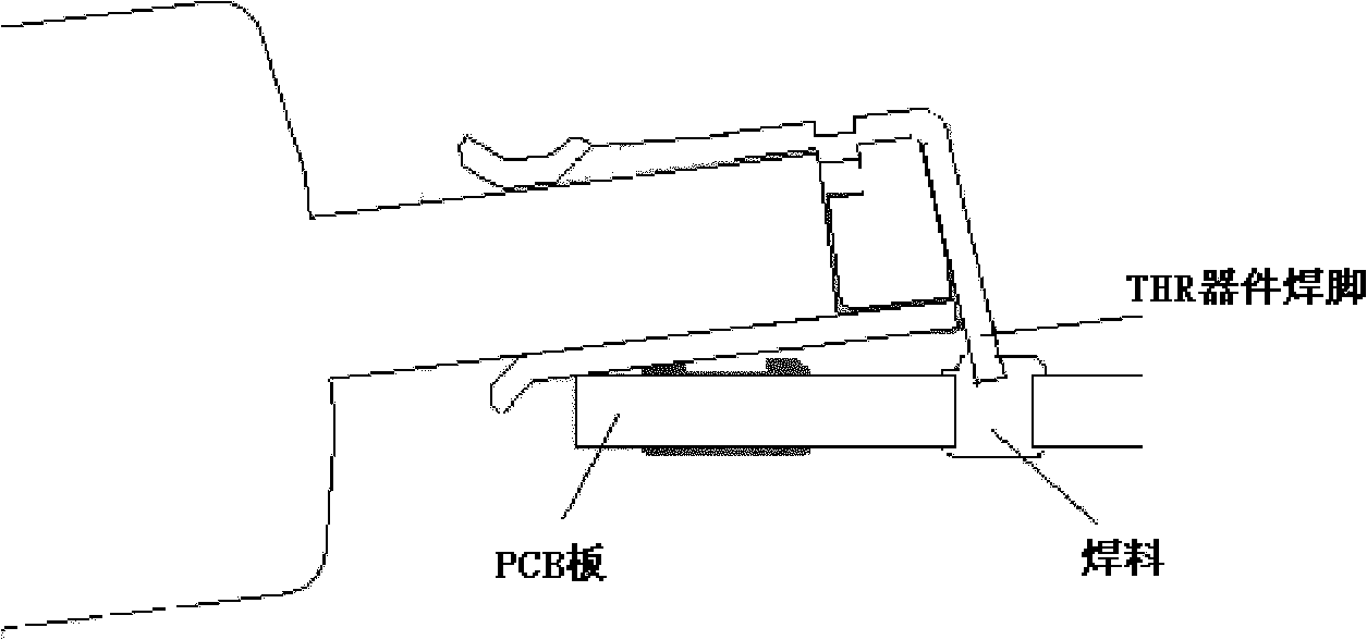
[0006] The inventor found during the research process that in the prior art, it is necessary to manually add tin to the position of the through-hole reflow pin hole plate and the solder pin position on the back of the THR device, which increases the manual soldering operation process and increases the operating hours, thereby increasing The manufacturing cost of the THR device is reduced; at the same time, the operator adds tin manually, which is difficult to achieve the consistency of the tin amount, which affects the welding strength of the THR device

Method used


Image

  • Method for soldering through-hole reflow device and printed circuit board
  • Method for soldering through-hole reflow device and printed circuit board
  • Method for soldering through-hole reflow device and printed circuit board

Examples


Embodiment Construction

[0029] In order to make the above objects, features and advantages of the present invention more comprehensible, the present invention will be further described in detail below in conjunction with the accompanying drawings and specific embodiments.

[0030] In view of this, the object of the present invention is to provide a soldering method and printed circuit board for through-hole reflow devices, which can effectively improve the soldering strength of THR devices without increasing the process, and can effectively control the soldering tin volume consistency.

[0031] refer to Figure 4 , is a flowchart of a soldering method for through-hole reflow devices according to an embodiment of the present invention. like Figure 4 As shown, the method described in the embodiment of the present invention includes the following steps:

[0032] Step S11: when performing the SMT process on the B side of the PCB board, automatically print a certain amount of solder paste for each sol...


PUM


Abstract

The embodiment of the invention discloses a method for soldering a through-hole reflow (THR) device, which comprises the following steps of: when performing a surface mounting technology (SMT) process for the back side of a printed circuit board (PCB), automatically printing a certain amount of solder cream for each solder leg hole at the back of a through-hole reflow solder leg hole plate; completing die bonding and reflow soldering on the back side of the PCB; when performing the SMT process for the front side of the PCB, automatically printing solder cream for each solder leg hole at the front side of the through-hole reflow solder leg hole plate; and completing the die bonding and reflow soldering on the front side of the PCB. The embodiment of the invention further also provides the PCB. By the embodiment of the invention, the soldering intensity of the through-hole reflow (THR) device can be effectively improved on the premise of not increasing working procedures, and the consistency of the soldering tin amount can be effectively controlled effectively.

Description

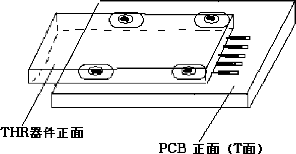
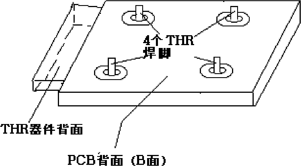
technical field [0001] The invention relates to the technical field of device welding, in particular to a method for welding through-hole reflow devices and a printed circuit board. Background technique [0002] More and more THR (Through-hole Reflow, through-hole reflow soldering) devices are used in electronic products, and most of the THR devices are interface devices, such as USB (Universal Serial BUS, Universal Serial Bus) connectors, earphone sockets connectors, etc. [0003] refer to Figure 1a and 1b , are the front and back views of a typical THR device. Commonly used THR devices are generally provided with several welding feet (such as Figure 1b shown in ). During the use of electronic products, when plugging and unplugging operations are performed between an external device and a THR device, the THR device is often subjected to external force. For example, when a USB cable is plugged in, an external impact will be brought to the USB connector, which requires...

Claims


Application Information

Patent Timeline
IPC IPC(8): H05K13/04H05K3/34
CPCH05K3/3447H05K3/1216H05K2203/1572
Inventor 乔吉涛陈晓晨丁海幸
Owner HUAWEI DEVICE CO LTD
Learn More