
Pressure swinging adsorption (PSA) gas separation device and control method thereof

A technology of pressure swing adsorption and gas separation, which is applied in separation methods, dispersed particle separation, chemical instruments and methods, etc. It can solve problems such as insufficient regeneration of adsorbents, decreased gas production rate of molecular sieves, and decreased gas production of equipment. The effect of reducing air consumption, reducing desorption and releasing air, and accelerating desorption time

Active Publication Date: 2011-07-06
上海瑞气气体科技有限公司
View PDF4 Cites 2 Cited by
  • Summary
  • Abstract
  • Description
  • Claims
  • Application Information

AI Technical Summary

Problems solved by technology

[0005] 1. The adsorbent has not been fully regenerated, which reduces the gas production rate of the molecular sieve at this time, resulting in a decrease in the actual rated equipment gas production, and a decrease in purity when the user turns on the rated design gas production of the equipment;
[0006] 2. Since the internal pressure of the adsorber is relatively high after pressure equalization, the gas adsorbed by the molecular sieve has not yet been desorbed with the pressure drop. At this time, the purge gas is opened and the venting pipeline is vented together, resulting in a waste of blowback product gas
[0007] 3. Only suitable for air separation equipment with small gas production

Method used


Image

  • Pressure swinging adsorption (PSA) gas separation device and control method thereof
  • Pressure swinging adsorption (PSA) gas separation device and control method thereof
  • Pressure swinging adsorption (PSA) gas separation device and control method thereof

Examples


Embodiment Construction

[0027] Below in conjunction with accompanying drawing and specific embodiment the present invention is described in further detail:

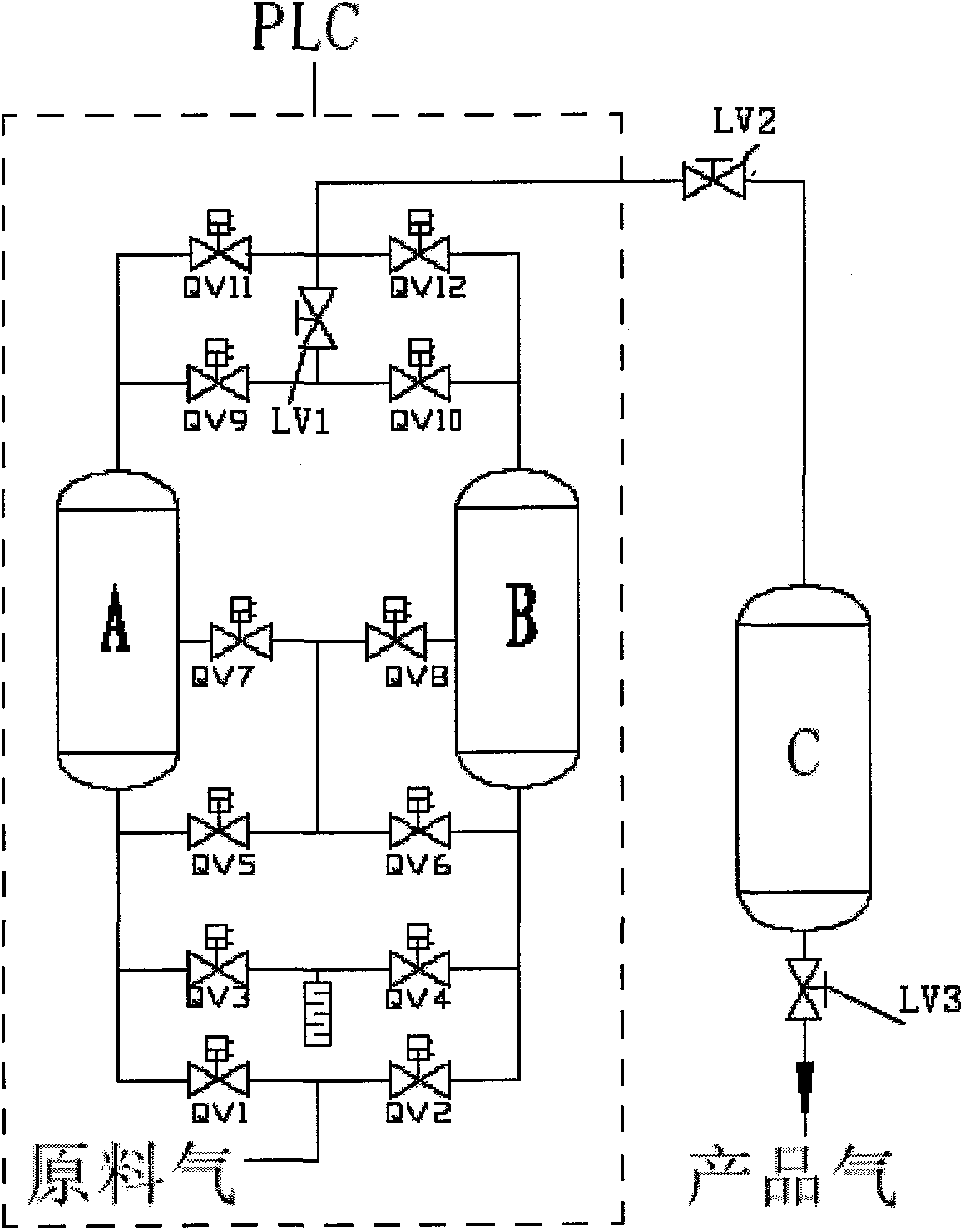
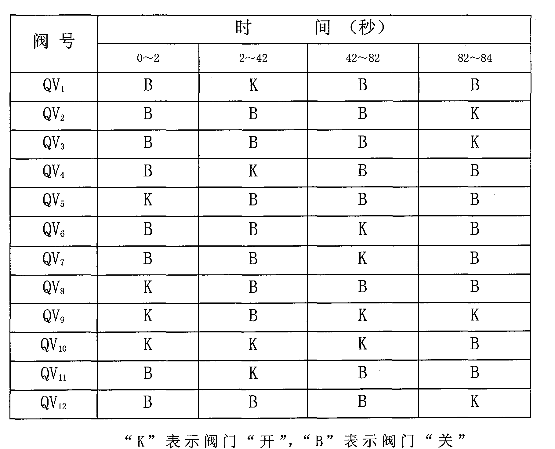
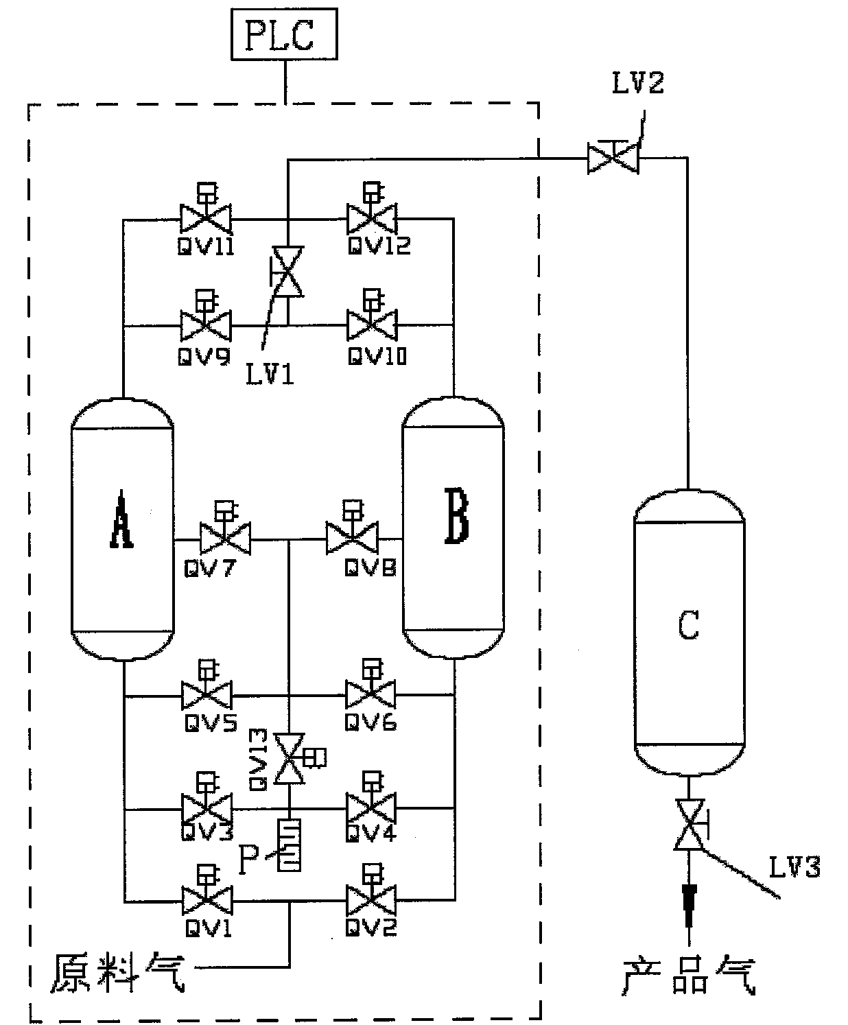
[0028] The device of the present invention includes: the first adsorption tower A and the second adsorption tower B are placed side by side on the foundation, a four-way pipeline is respectively connected to the bottom of the first adsorption tower A, the first pipeline pneumatic valve QV 1 , The third pipeline pneumatic valve QV 3 and the third pipe pneumatic valve QV 5 One end of the first adsorption tower A is connected to the seventh pipeline pneumatic valve QV 7 A three-way pipe connects the top of the first adsorption tower A and the ninth pipe pneumatic valve QV respectively. 9 And the eleventh pipeline pneumatic valve QV 11 ; Use a four-way pipeline to connect the bottom of the second adsorption tower B and the pneumatic valve QV of the second pipeline respectively 2 , the fourth pipeline pneumatic valve QV 4 And the sixth pipeline ...


PUM


Abstract

The invention relates to a pressure swing adsorption (PSA) gas separation device and a control method thereof. In the invention, a middle escape pipe pneumatic valve QV13 is additionally arranged on the basis of the prior art; the connection structure of pipes is as follows: the position of an original pipe pneumatic valve QV-12 is not changed, a four-way pipe of a connecting pipe pneumatic valves QV5, QV6, QV7 and QV8 is changed into a five-way pipe that is respectively connected with the connecting pipe pneumatic valves QV5, QV6, QV7 and QV8 and a connecting pipe pneumatic valves QV13, a three-way pipe of an original connecting pipe pneumatic valves QV3 and QV4 and an evacuation silencer is changed into a four-way pipe that is respectively connected with the other end of the connecting pipe pneumatic valve QV13, the connecting pipe pneumatic valves QV3 and QV4 and the evacuation silencer, and other pipes are not changed; desorption of a regenerated adsorbent is accelerated so as to ensure that the complete desorption of the regenerated adsorbent makes a good foundation for next adsorption and improve the adsorption property of a molecular sieve; and regenerated finished gas for purging is saved, the desorption air bleeding is decreased, the air bleeding time is shortened, the air consumption is decreased, and the user running energy consumption and the production cost can belowered.

Description

technical field [0001] The invention relates to a pressure swing adsorption gas separation device, in particular to the structure of the device and the method for controlling the pressure swing adsorption separation device. Background technique [0002] The most commonly used method for the equipment that uses a fixed adsorbent bed for pressure swing adsorption to separate mixed gases is to use a fixed adsorption cycle. Its working principle is: when a container with adsorbent (referred to as the adsorption tower) is raising the pressure to produce gas, at the same time the other adsorption tower is venting and reducing the pressure to desorb and regenerate, and the two towers are switched through a fixed adsorption cycle. In the working mode, each tower completes gas production and desorption regeneration once, which is called an adsorption cycle; such an alternating cycle works to continuously generate product gas. The structural diagram of the process equipment is shown i...

Claims


Application Information

Patent Timeline
IPC IPC(8): B01D53/047
Inventor 张军刘益民韩维峰申春午沈闻皓谢贵琴
Owner 上海瑞气气体科技有限公司
Learn More