Air-conditioning heat exchanger

A heat exchanger and air conditioner technology, applied in indirect heat exchangers, heat exchanger types, heat exchange equipment, etc., can solve the problems of increasing compressor workload, excessive local pressure drop, and reduced heat exchange efficiency. To achieve the effect of reducing the resistance along the way, reducing the working load and reducing the transmission power

Inactive Publication Date: 2011-07-06
NINGBO HICON IND
View PDF7 Cites 4 Cited by
  • Summary
  • Abstract
  • Description
  • Claims
  • Application Information

AI Technical Summary

Problems solved by technology

[0002] At present, the heat exchanger used in the existing air conditioner is composed of an outer tube and an inner tube, wherein the outer tube is a straight tube, the inner tube is a spiral tube with equal pitch, and the inner wall of the outer tube is sealed with the spiral outer surface of the inner tube. The spiral pipe, the refrigerant enters from the entrance of the spiral pipe and flows through the spiral pipe, the refrigerant intermediate medium flows in the inner pipe, the flow direction between the refrigerant and the intermediate medium is opposite, and the heat exchange is performed through the spiral inner pipe wall. The disadvantage of the heat exchanger is that the refrigerant undergoes a phase change in the process of heat exchange with the intermediate medium, that is, it changes from the initial gaseous state to a liquid state, and the volume and pressure of the refrigerant change greatly, while the spiral pipe caused by the equidistant spiral pipe The cross-sectional area of ​​the refrigerant remains unchanged, and it is impossible to make corresponding adjustments. Therefore, the local pressure drop of the refrigerant in the heat exchange process is too large and the distribution is uneven, and the flow rate of the refrigerant is unstable, which in turn reduces the heat exchange efficiency. The total pressure loss in the heat exchange process is too large, which increases the workload of the compressor. In addition, the uneven pressure of the heat exchanger causes the total resistance of the refrigerant in the heat exchanger to be large, which reduces the delivery efficiency of the refrigerant.

Method used


Image

  • Air-conditioning heat exchanger
  • Air-conditioning heat exchanger
  • Air-conditioning heat exchanger

Examples


Embodiment Construction

[0015] A specific embodiment of the present invention will be described in detail below in conjunction with the accompanying drawings, but it should be understood that the protection scope of the present invention is not limited by the specific embodiment.

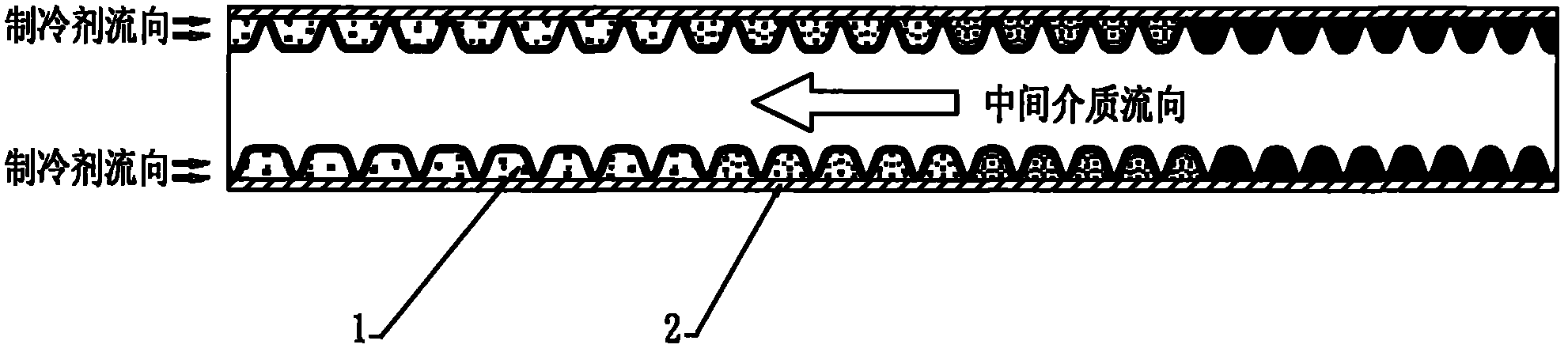
[0016] Such as figure 1 As shown, the air conditioner heat exchanger of the present invention is composed of an outer tube 2 and an inner tube 1, the inner tube 1 is a spiral tube, the outer tube 2 and the inner tube 1 are fitted together, the inner wall of the outer tube 2 and the inner tube 1 The spiral outer wall is enclosed to form a spiral pipe, the refrigerant flows in from the entrance of the spiral pipe and flows through the spiral pipe, and the refrigeration intermediate medium flows in the inner pipe, and the flow direction between the refrigerant and the intermediate medium is opposite and is carried out through the spiral inner pipe wall. heat exchange. The pitch of the spiral inner tube forms a gradual change...


PUM


Abstract

The invention discloses an air-conditioning heat exchanger which comprises an outer pipe and an inner pipe, wherein the outer pipe is a straight pipe, the inner pipe is a spiral pipe, and the outer pipe and the inner pipe are mutually sleeved. The inner wall of the outer pipe and the outer spiral wall of the inner pipe are enveloped to form a spiral pipeline, a refrigerant enters through an inlet of the spiral pipeline and flows across the spiral pipeline, a refrigerating intermediate medium relatively flows in the inner pipe, the refrigerant exchanges heat with the intermediate medium through the wall of the inner spiral pipe, and the thread pitch of the inner spiral pipe is designed as gradual change according to the change situation of volume and pressure drop caused by the phase change of the refrigerant in the heat exchange process. Through the gradual change design for the thread pitch of the inner spiral pipe of the heat exchanger, a refrigerant channel can be adapted to the volume and pressure change of the refrigerant due to heat exchange, the stable pressure and the flow velocity of the refrigerant in the heat exchanger can be ensured, and the efficiency of the heat exchanger can be guaranteed; meanwhile, pressure loss in the heat exchange process is reduced, and the working load of a compressor is reduced; in addition, the total way resistance of the refrigerant is simultaneously reduced, and the delivery power of the refrigerant is reduced.

Description

technical field [0001] The invention relates to a heat exchanger, in particular to a heat exchanger used in an air conditioner. Background technique [0002] At present, the heat exchanger used in the existing air conditioner is composed of an outer tube and an inner tube, wherein the outer tube is a straight tube, the inner tube is a spiral tube with equal pitch, and the inner wall of the outer tube is sealed with the spiral outer surface of the inner tube. The spiral pipe, the refrigerant enters from the entrance of the spiral pipe and flows through the spiral pipe, the refrigerant intermediate medium flows in the inner pipe, the flow direction between the refrigerant and the intermediate medium is opposite, and the heat exchange is performed through the spiral inner pipe wall. The disadvantage of the heat exchanger is that the refrigerant undergoes a phase change in the process of heat exchange with the intermediate medium, that is, it changes from the initial gaseous sta...

Claims


Application Information

Patent Timeline
Patent Type & Authority Applications(China)
IPC IPC(8): F25B39/00F28D7/10F28F1/00
Inventor 陈越增王立明邓军琦汪志强
Owner NINGBO HICON IND
Why Eureka
Try Eureka