Relay network system and downlink resource allocation method thereof
A technology of resource allocation and relay network, applied in the field of communication, can solve problems such as insufficient utilization of resources and limitation of relay network performance.
- Summary
- Abstract
- Description
- Claims
- Application Information
AI Technical Summary
Problems solved by technology
Method used
Image

Examples
Embodiment 1
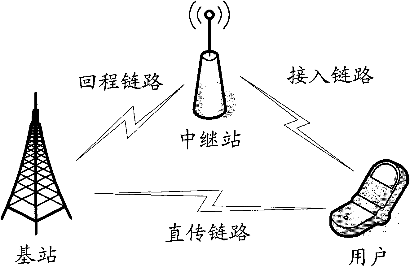
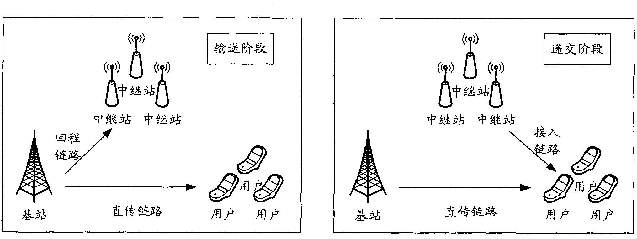
[0111] In a relay network with 1 base station eNB, 2 relay stations RN1, RN2, and 3 users UE1, UE2, UE3, user 1 and user 2 are served by RN1 and RN2 respectively, and UE3 is directly served by the base station. The system can allocate resources to 5 RBs, denoted as RB1, RB2, RB3, RB4, RB5, and the average obtained resource quantization value of user i is known as T i . In the submission stage, the quantized value of the channel condition of user i on RBk is SINR2 U i,k , have exceeded the basic threshold THb2; in the delivery phase, the quantized channel status value of user i on RBk is SINR1 U i,k , the channel status quantization value of relay station j on the RBk in the transmission phase is SINR1 R j,k , have exceeded the basic threshold THb1.
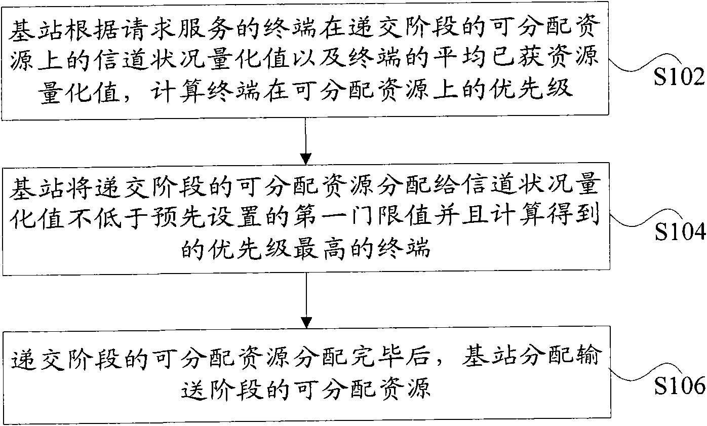
[0112] 1. Firstly, the resource allocation in the submission stage is carried out. For RB1, the priorities of the three users are respectively obtained according to the following methods:
[0113] P ...
PUM
 Abstract
Description
Claims
Application Information
PatSnap Eureka turns technology decisions into work you can execute. Powered by our Innovation Knowledge Graph, it runs expert workflows across engineering, life sciences, materials and intellectual property. Get your review-ready output in minutes.


