Damping balance high-speed milling tool and design method thereof

A design method and high-speed milling technology, applied to milling cutters, milling machine equipment, metal processing equipment, etc., can solve the problems of uneven distribution of milling cutter quality, failure to meet milling cutter dynamic balance and safety requirements, etc. Effects of milling vibration, avoiding milling cutter resonance, and eliminating principle errors

Inactive Publication Date: 2011-07-13
HARBIN UNIV OF SCI & TECH
View PDF0 Cites 8 Cited by
  • Summary
  • Abstract
  • Description
  • Claims
  • Application Information

AI Technical Summary

Problems solved by technology

However, the quality of the milling cutter designed by this method is in an uneven distribution state, which ca

Method used


Image

  • Damping balance high-speed milling tool and design method thereof
  • Damping balance high-speed milling tool and design method thereof
  • Damping balance high-speed milling tool and design method thereof

Examples


Embodiment 1

[0023] A design method for a vibration-reducing balanced high-speed milling cutter, the method includes the following steps:

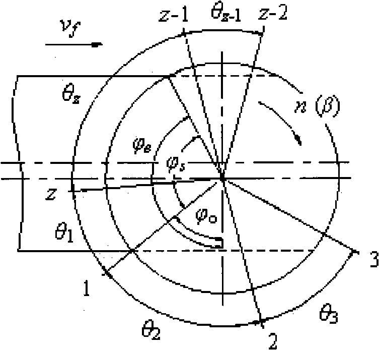
[0024] 1. Based on the single-tooth dynamic cutting force model, a multi-tooth dynamic cutting force model of high-speed milling cutter is established.

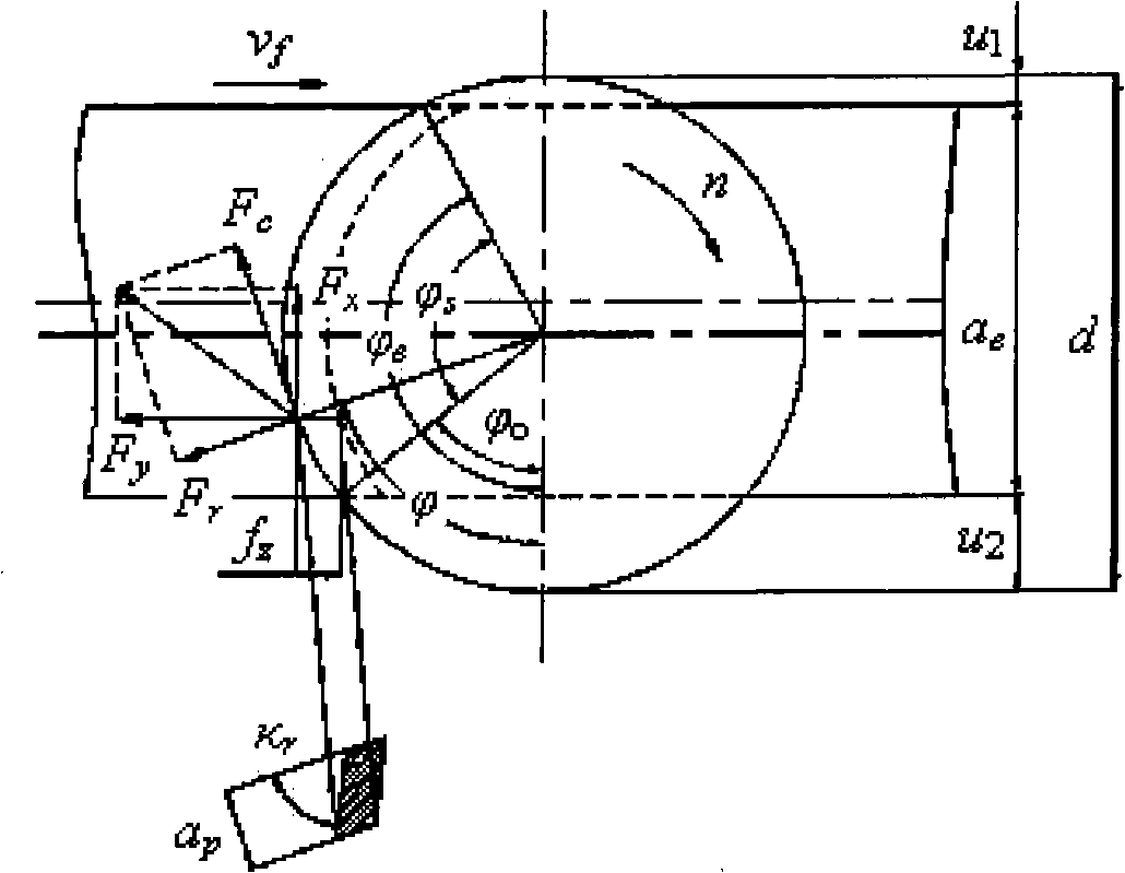
[0025] When the high-speed milling cutter is cutting, due to the intermittent cutting of the cutter teeth and the change of the cutting thickness, the cutting force whose waveform changes periodically becomes one of the main exciting forces that cause the vibration of the tool system. Single-tooth cutting methods such as figure 1 Shown:

[0026] Tooth cutting contact angle and is the feed direction angle for:

[0027]

[0028] Cutting force F along the tangential direction of the milling cutter e , radial cutting force F r and axial cutting force F z Can be expressed as:

[0029]

[0030]

[0031]

[0032] In the formula: p is the unit cutting force (N / mm 2 );a p is the milling...

Embodiment 2

[0145] A vibration-damping and balanced high-speed milling cutter designed by the above method. The cutter teeth are under the constraint of the structural strength of the high-speed milling cutter. Through the analysis of the dynamic balance accuracy of the milling cutter, the behavior modeling technology is used to complete the cutter tooth distribution and chip volume. The optimized groove design meets the safety and dynamic balance accuracy requirements of the milling cutter, and obtains high-speed milling cutter teeth that meet the vibration reduction requirements.


PUM


Abstract

The invention discloses a damping balance high-speed milling tool and a design method thereof. The excitation energy during high-speed milling of the tool is concentrated; if the number of teeth of the tool is improperly selected, the excitation frequency approaches the natural frequency of the milling tool, thus relatively strong vibration appears, and the requirements of high-efficiency and high-speed cutting processing cannot be met. The method disclosed by the invention comprises the following steps of: (1) establishing a multi-tooth dynamic cutting force model of the high-speed milling tool based on a single-tooth dynamic cutting force model; (2) establishing a multi-tooth cutting dynamic cutting force spectrum model; (3) establishing a cutting stability evaluation model of the high-speed milling tool; (4) analyzing influence of the tool tooth distribution on the dynamic cutting force spectrum, and optimizing the tooth pitch of the high-speed milling tool; and (5) under the constraint conditions of the structural strength of the high-speed milling tool, analyzing the dynamic balance precision of the milling tool, and implementing the optimal design of the tool tooth distribution and a scraps containing groove by use of the behavior modeling technology so as to meet the requirements for the milling tool safety and dynamic balance precision and obtain a high-speed milling tool design scheme meeting the damping requirements. The method disclosed by the invention is used for designing the damping balance high-speed milling tool.

Description

Technical field: [0001] The invention relates to a high-speed milling cutter with damping balance and a design method thereof, in particular to a high-speed milling cutter with unevenly distributed cutter teeth and a dynamic balance design method thereof. Background technique: [0002] In the process of high-speed milling, due to the high speed of the tool, strict dynamic balance and safety requirements are put forward for the high-speed milling cutter. At present, the known high-speed milling cutter has the characteristics of good dynamic balance, high safety and high application speed due to the uniform distribution of cutter teeth. However, the excitation energy in high-speed milling of such tools is concentrated, and the frequency of the excitation force depends on the rotation speed and the number of teeth of the milling cutter. If the number of teeth of the cutter is not properly selected, the excitation frequency will be close to the natural frequency of the milling c...

Claims


Application Information

Patent Timeline
IPC IPC(8): B23C5/00
Inventor 郑敏利姜彬
Owner HARBIN UNIV OF SCI & TECH
Why Eureka
Try Eureka