
Multi-flute ball end mill

a ball end mill and multi-flute technology, applied in the direction of metal-working equipment, milling equipment, manufacturing tools, etc., can solve the problems of reducing the cutting performance of the ball edge, reducing the cutting load of the ball edge unable to prevent the blockage of the chip during high-feed rough machining, etc., to achieve excellent chip discharge performance, enhance the rigidity of the edge tip, and effectively suppress the increase of the cutting load of the ball edg

Active Publication Date: 2018-12-25
HITACHI TOOL ENG LTD
View PDF24 Cites 2 Cited by
  • Summary
  • Abstract
  • Description
  • Claims
  • Application Information

AI Technical Summary

Benefits of technology

The present invention describes a multi-flute ball end mill that improves chip discharge performance in high-feed rough machining of difficult-to-cut materials by increasing the occupation area of the chip pocket and securing the width of the third face of each ball edge. This results in enhanced edge tip rigidity and effective suppression of cutting load, reducing chipping and breaking and achieving high-quality machined surfaces.

Problems solved by technology

Thus, clogging of chips during high-feed rough machining cannot be prevented.
Therefore, there is a concern that the cutting resistance during high-feed rough machining may increase markedly and the cutting performance may degrade.
However, in the ball end mill described in PTL 3, a cutting operation cannot be performed by the vicinity of the rotation center.
Therefore, there is a high possibility that the machined face quality of a work material may deteriorate in high-feed rough machining.
However, in this ball end mill, the degree of curvature of the ball edges is small.
Therefore, there is a concern that the cutting resistance during high-feed rough machining may increase markedly and the cutting performance may degrade.

Method used


Image

  • Multi-flute ball end mill
  • Multi-flute ball end mill
  • Multi-flute ball end mill

Examples


Embodiment Construction

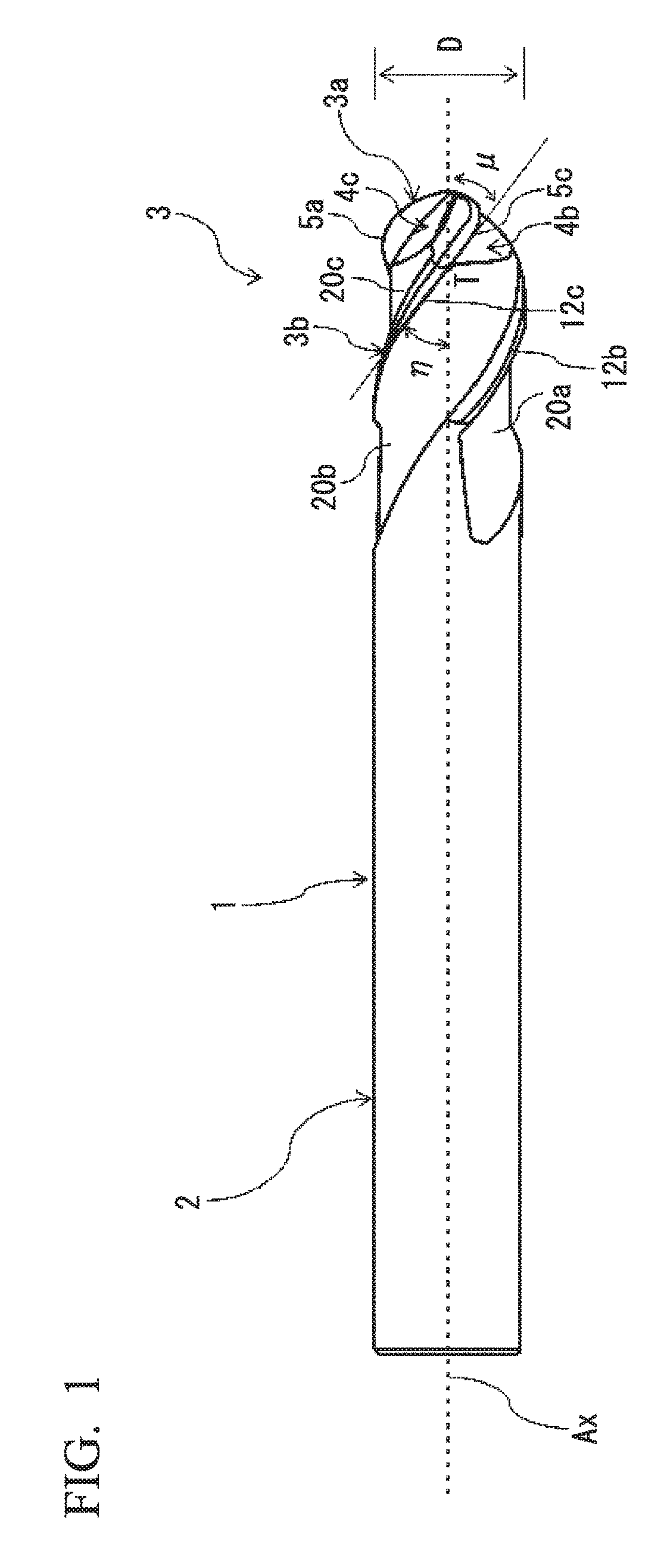
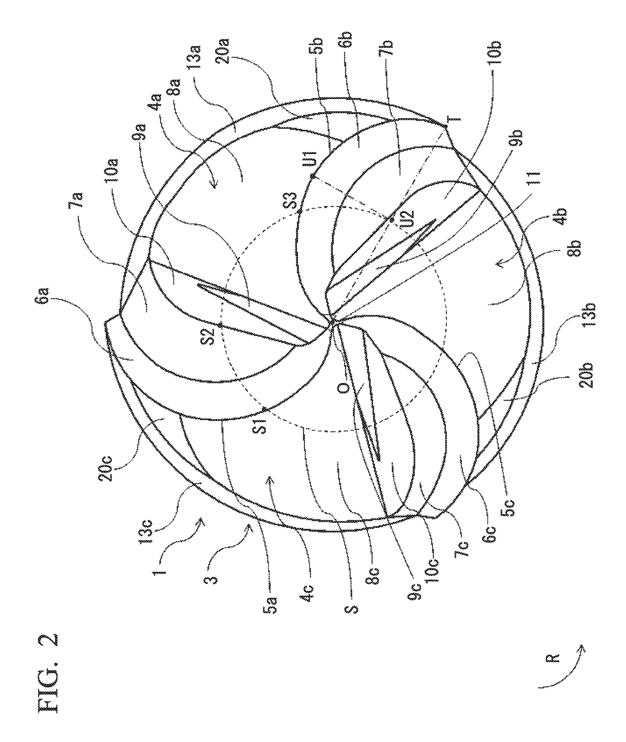
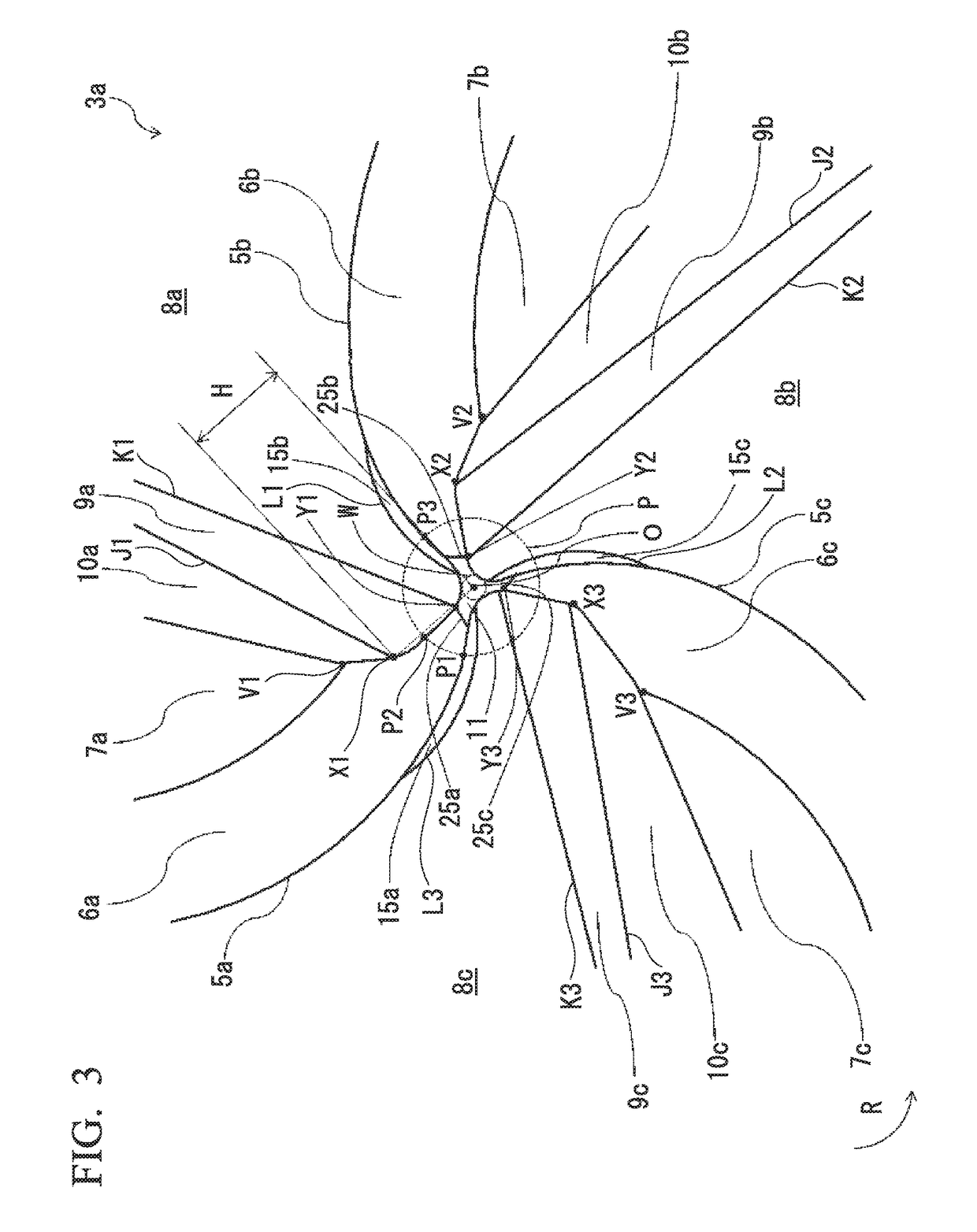
[0030]As an embodiment (hereinafter referred to as “present embodiment”) of a multi-flute ball end mill of the present invention, a solid three-flute ball end mill made of cemented carbide will be described below in detail as an example. The multi-flute ball end mill of the present embodiment includes: a shank portion configured to rotate about a rotational axis; and a cutting edge portion provided on a tip side of the shank portion in a direction of the rotational axis. The cutting edge portion has a shape that is rotationally symmetrical around the rotational axis, and has: a ball edge portion formed at a tip of the cutting edge portion in the direction of the rotational axis; and a peripheral cutting edge portion that is continuous with a posterior end of the ball edge portion in the direction of the rotational axis. The ball edge portion has: three or more ball edges; and the same number of gashes as the ball edges, gashes being formed between each adjacent pair of the ball edge...


PUM


Abstract

A multi-flute ball end mill of the present invention includes: a shank portion configured to rotate about a rotational axis; a cutting edge portion; three or more ball edges formed on the cutting edge portion; gashes formed between the ball edges; peripheral cutting edges continuous with end portions of the ball edges on the shank portion side; and flutes formed between the peripheral cutting edges continuously with the gashes. The degree of curvature of the ball edges is 35% to 55%. Each of the gashes includes four faces of a rake face of each of the ball edges, a gash wall face, a first gash face, and a second gash face. The second gash face is formed such that the closer the second gash face is to the rotation center point, the more inwardly the second gash face enters a second face of each of the ball edges.

Description

TECHNICAL FIELD[0001]The present invention relates to a multi-flute ball end mill according to which high-quality machined surfaces can be obtained even in a case where high-feed rough machining is performed on high-hardness difficult-to-cut materials, such as hot-forged steel used for various kinds of metal dies.[0002]Priority is claimed on Japanese Patent Application No. 2014-219718, filed Oct. 28, 2014, the content of which is incorporated herein by reference.BACKGROUND ART[0003]As ball end mills with long lifespan that are used for manufacture of various kinds of components in the automobile industry, the electronic industry, or the like and that can cut high-hardness metal dies with high efficiency, multi-flute ball end mills that have three or more ball edges and are made of cemented carbide are widely used.[0004]PTL 1 discloses a ball end mill in which each of ball edges is constituted with a first cutting portion and a second cutting portion, the curvature radius of the firs...

Claims


Application Information

Patent Timeline
Patent Type & Authority Patents(United States)
IPC IPC(8): B23C5/00B23C5/10
CPCB23C5/1009B23C5/10B23C2210/0428B23C2220/60B23C2210/202B23C2210/40B23C2210/54B23C2210/0435B23C2210/084B23C2210/12B23C2210/08
Inventor SAKAI, SHINJIROHYOKOKAWA, MITSUHIROSATOU, TOMOHIRO
Owner HITACHI TOOL ENG LTD
Learn More