
Cutting assembly with multiple cutting tools for milling

a technology of cutting assembly and milling, which is applied in the direction of manufacturing tools, metal-working equipment, milling equipment, etc., can solve the problems of not being suitable for other kinds of milling operations, and the prior art cutting tools do not provide satisfactory results, etc., to achieve high speed, high quality of machining, and large cut depth

Active Publication Date: 2021-04-01
SECO TOOLS AB
View PDF0 Cites 0 Cited by
  • Summary
  • Abstract
  • Description
  • Claims
  • Application Information

AI Technical Summary

Benefits of technology

The present invention provides a cutting assembly for milling operations with high speeds and large depth of cut. The assembly includes a rigid cutting tool that can be easily grinded to the preferred geometry and used in different tool holders. The cutting tools are positioned in a correct position for machining, and the assembly has low tendency for vibration and chatter. The assembly also provides good chip evacuation and flexibility for users. The threaded hole in the tool holder increases the clamping force and retains it at greater cutting speeds. The presence of a central tool mounting hole increases flexibility for the tool holder.

Problems solved by technology

The tool described in EP2818268 is adapted for slot milling and would not be suitable for other kinds of milling operations, in particular not for milling operations with high speeds and feeds and a large depth of cut.
In many milling operations, such as demanding operations using high feeds and speeds and a large depth of cut, the cutting tools according to the prior art do not provide satisfactory results.

Method used


Image

  • Cutting assembly with multiple cutting tools for milling
  • Cutting assembly with multiple cutting tools for milling

Examples


Embodiment Construction

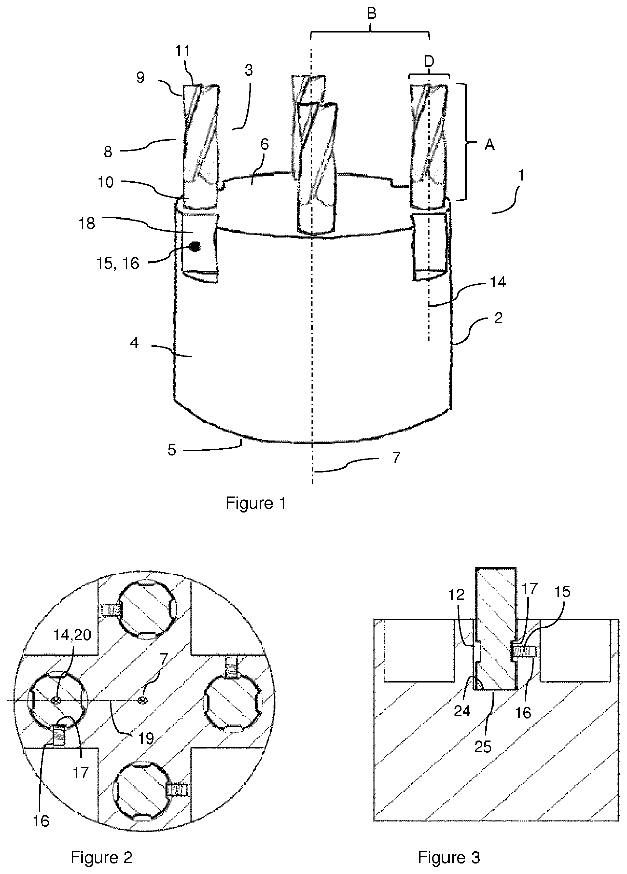
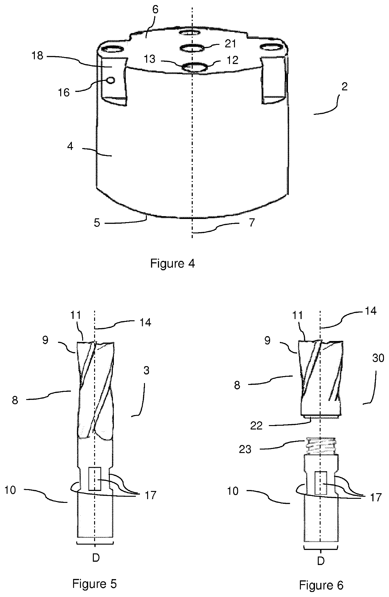
[0048]A cutting assembly, a tool holder and a cutting tool according to the invention will now be described with reference to FIGS. 1-6. The cutting assembly, illustrated in FIGS. 1-3, comprises a tool holder 2 and four milling cutting tools 3 arranged in the tool holder. The tool holder has a tool holder body 4, a rear coupling end 5, and a front end 6. A tool holder central axis 7, around which the tool holder is rotatable when mounted to a machine tool spindle, extends through the tool holder body 4 between the front end 6 and the rear coupling end 5. The rear coupling end 5 is arrangeable to a machine tool spindle (not shown), either directly or via a basic holder of a modular tooling system, such as Coromant Capto®. Each cutting tool comprises a cutting portion 8 with four peripheral cutting edges 9 (of which the most radially distal peripheral cutting edge of one cutting tool is indicated in the figures) and a shank 10 (of which the major part is located within the tool holder...


PUM


Abstract

A cutting assembly for milling includes at least two milling cutting tools with shanks that are arranged in a rotatable tool holder at a distance from the central axis of the tool holder, such that an operational region of a cutting portion of each cutting tool is primarily facing outwards, in a radial direction, from the tool holder central axis.

Description

TECHNICAL FIELD[0001]The invention relates to a cutting assembly for milling as well as a tool holder, a cutting tool shank and a cutting tool for use in such assembly.BACKGROUND ART[0002]In the art of milling it is known to use milling tools having a plurality of indexable inserts arranged at the periphery of a milling tool body. An insert used in this kind of tool often has a through hole used for mounting the insert to the milling tool body, for example using a screw.[0003]Document EP2818268 shows such a tool where a number of cutting inserts are mounted around the periphery of a holder and used as indexable inserts therein. The tool described in EP2818268 is adapted for slot milling and would not be suitable for other kinds of milling operations, in particular not for milling operations with high speeds and feeds and a large depth of cut.[0004]In many milling operations, such as demanding operations using high feeds and speeds and a large depth of cut, the cutting tools accordin...

Claims


Application Information

Patent Timeline
IPC IPC(8): B23C5/10
CPCB23C5/10B23C2210/03B23C2210/02B23C5/006
Inventor HAEX, HENK
Owner SECO TOOLS AB
Learn More