Machine tool for generating optimum acceleration/deceleration

Active Publication Date: 2017-03-30
FANUC LTD
View PDF3 Cites 6 Cited by
  • Summary
  • Abstract
  • Description
  • Claims
  • Application Information

AI Technical Summary

Benefits of technology

The present invention is about improving the movements of a machine tool to achieve high-quality machining. Conventionally, the movements of the machine tool are determined by an engineer based on their expertise, but this may not always result in an optimal movement. The invention introduces machine learning to determine the optimal movement of each axis, allowing for better and faster machining while maintaining surface quality.

Problems solved by technology

Further, although a machining object has an allowable error and a target machining time, an operator of a machine tool adjusts, while confirming the machining surface quality of the machining object, the allowable error and the target machining time by changing an acceleration / deceleration time constant or changing a speed commanded in a program.
However, when a tool is rapidly decelerated and accelerated at a corner part or near a curve part under such a setting, there is a likelihood that vibration occurs in a machine to degrade machining surface quality (a machining surface is scratched).
When a speed of a tool suddenly changes in various machining such as lathe-turning shown in FIG. 8A and boring machining shown in FIG. 8B, vibration occurs in a machine due to the impact of the change, which causes the degradation of machining surface quality at a corner part or a curve part.
When adjusting an acceleration / deceleration while balancing an improvement in machining surface quality and reduction in a machining time in consideration of each element associated with the movement of an axis so as to prevent such phenomena, an operator has to expend much effort and may still not be able to optimize a speed or an acceleration.
As a response to such problems, the prior art techniques disclosed in Japanese Patent Application Laid-open No. 2003-058218 and Japanese Patent Application Laid-open No. 2006-043836 can only deal with situations adapted to a prepared parameter set or a machining pattern, and cannot flexibly deal with a diversity of situations.

Method used


Image

  • Machine tool for generating optimum acceleration/deceleration
  • Machine tool for generating optimum acceleration/deceleration
  • Machine tool for generating optimum acceleration/deceleration

Examples


Embodiment Construction

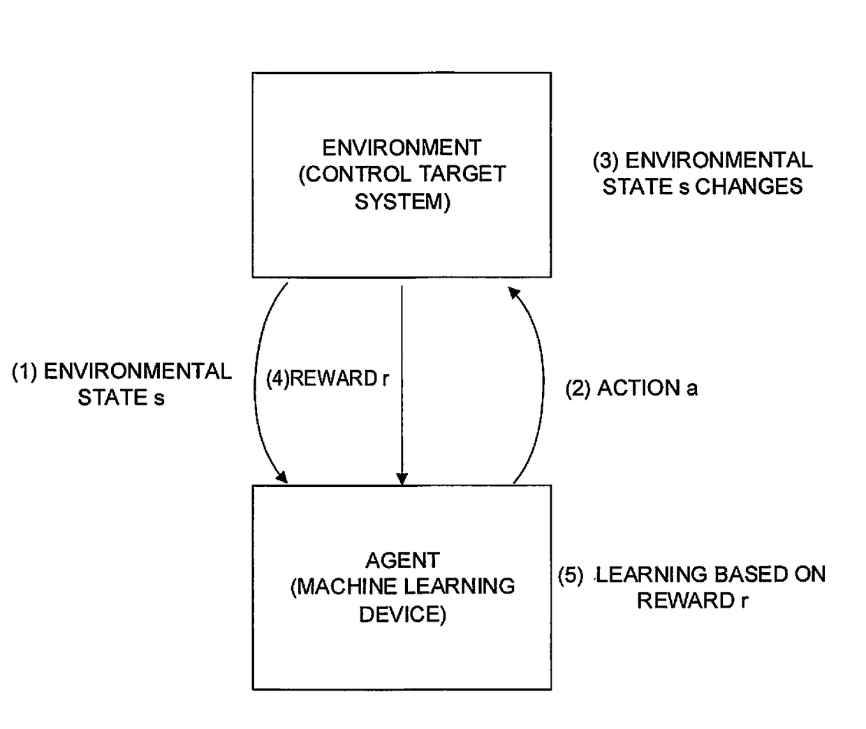
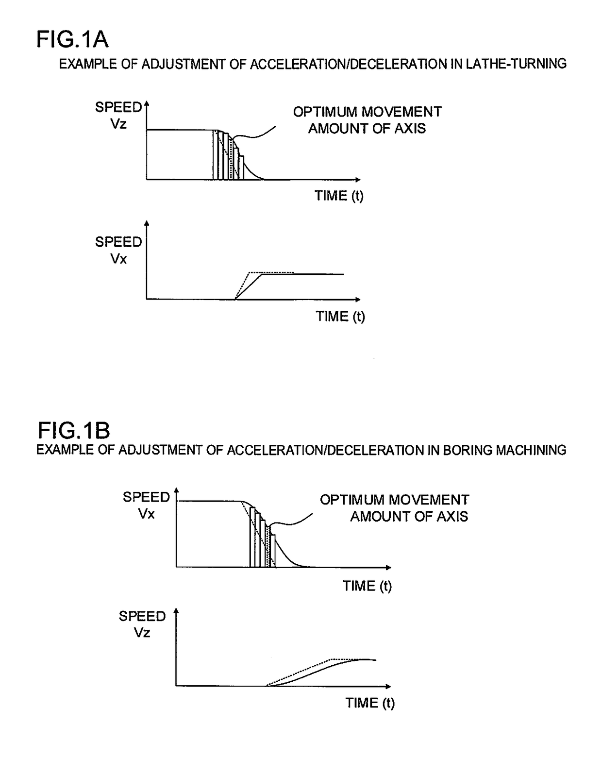
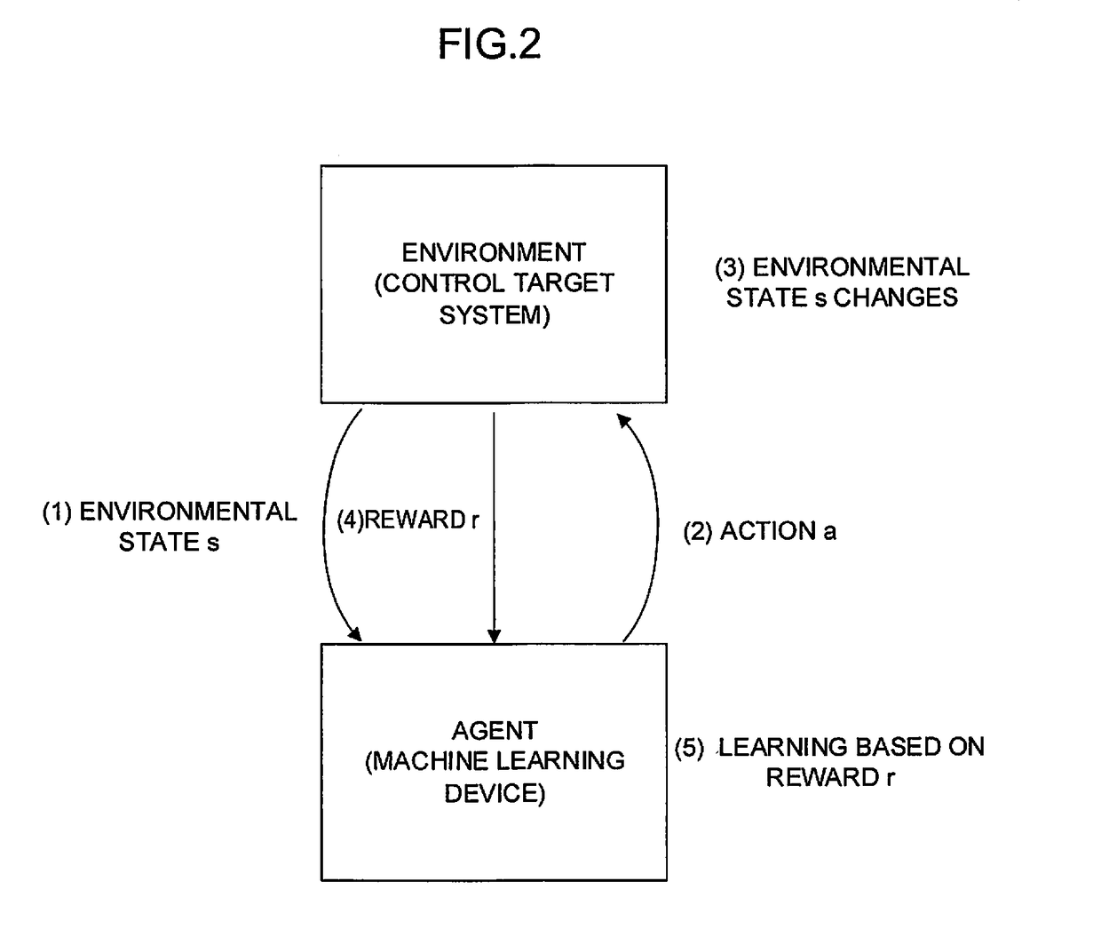
[0028]In the present invention, a machine learning device acting as artificial intelligence is introduced into a machine tool that machines a workpiece, and machine learning is performed about the determination of a movement amount to adjust an acceleration / deceleration of each axis of the machine tool in the machining of the workpiece based on a machining program, whereby the acceleration / deceleration (a change in a movement amount) of each axis of the machine tool is adjusted to be optimum at each time in the machining of the workpiece as shown in FIGS. 1A and 1B. In the adjustment of the acceleration / deceleration of each axis, the faster movement of a tool, the avoidance of the deviation of a tool path, and the avoidance of the occurrence of an impact are targeted. Thus, the machining of a workpiece maintaining its machining surface quality is realized in a shorter period of time.

[0029]Hereinafter, a description will be briefly given of machine learning to be introduced into a ma...


PUM


Abstract

A machine tool includes an operation evaluation section that evaluates an operation thereof and a machine learning device that performs the machine learning of a movement amount of an axis thereof. The machine learning device calculates a reward based on state data including the output of the operation evaluation section, performs the machine learning of the determination of the movement amount of the axis, and determines the movement amount of the axis based on a machine learning result and outputs the determined movement amount. The machine learning device performs the machine learning of the determination of the movement amount of the axis based on the determined movement amount of the axis, the acquired state data, and the calculated reward.

Description

BACKGROUND OF THE INVENTION[0001]1. Field of the Invention[0002]The present invention relates to a machine tool and, in particular, to a machine tool that generates an optimum acceleration / deceleration in controlling each axis.[0003]2. Description of the Related Art[0004]In conventional machining of a component, a mold, or the like, a machining program is generated and a machine tool is controlled based on the generated machining program to perform the machining. A machining speed for performing machining is commanded as a movement speed of an axis in a machining program, which is a maximum speed of the relative movement (tool movement) between a tool and a machining object. However, actually, movement data in which a movement speed of each axis is varied according to an acceleration / deceleration time constant of each axis is output to a machine tool at the time of starting machining, or in a corner part, a curve part, or the like. Further, although a machining object has an allowab...

Claims


Application Information

Patent Timeline
IPC IPC(8): G05B19/408G05B19/402G06N20/00
CPCG05B19/4083G05B2219/39295G05B19/402G05B19/416G05B2219/31412G06N20/00G05B13/0265G05B19/4163G05B2219/33056G05B2219/41367G05B2219/49061
Inventor KOGA, DAIJIROU
Owner FANUC LTD
Why Eureka
Try Eureka