Flexible substrate position control device

a technology of position control device and flexible substrate, which is applied in the direction of transportation and packaging, sustainable manufacturing/processing, final product manufacturing, etc., can solve the problems of difficult to maintain difficult to maintain the flexible substrate at a constant transport height, and the tendency of flexible substrate to sag prominently, etc., to achieve high-quality processing, effective inhibit the occurrence of sagging and wrinkles, and accommodate the effect of low cos

Inactive Publication Date: 2012-02-09
FUJI ELECTRIC CO LTD
View PDF4 Cites 7 Cited by
  • Summary
  • Abstract
  • Description
  • Claims
  • Application Information

AI Technical Summary

Benefits of technology

[0031]As has been previously described, the flexible substrate position control device according to the present invention is able to effectively inhibit the occurrence of sagging and wrinkling of a flexible substrate when carrying out processing such as deposition while transporting a band-shaped flexible substrate, and together with realizing high-quality processing by maintaining a constant position in the direction of width, reciprocating processes that include transport of a flexible substrate in opposite directions can also be accommodated inexpensively.

Problems solved by technology

Although the latter offers advantages such as having a small installation area and being more resistance to soiling of the substrate surface in comparison with the former, if the transport span becomes excessively long, it becomes difficult to maintain a constant transport height in opposition to gravity, thereby resulting in the occurrence of wrinkles in the surface of the flexible substrate or causing the tendency for the flexible substrate to sag to become prominent.
However, since this device repeats gripping, pulling and release of the flexible substrate, it is difficult to maintain the flexible substrate at a constant transport height, and is also unable to realize a continuous deposition device that carries out deposition while continuously transporting flexible substrates.
Although this device is advantageous in terms of deploying the flexible substrate and adjusting the transport height of the flexible substrate, it cannot be applied to a reciprocating deposition process that includes transport of flexible substrates in the opposite direction.
If flexible substrates are transported in the opposite direction, the lifting force and lowering force attributable to the above-mentioned deflection angles act in opposite directions, thereby causing the problem of the clamping rollers 30 and 30′.

Method used


Image

  • Flexible substrate position control device
  • Flexible substrate position control device
  • Flexible substrate position control device

Examples


first embodiment

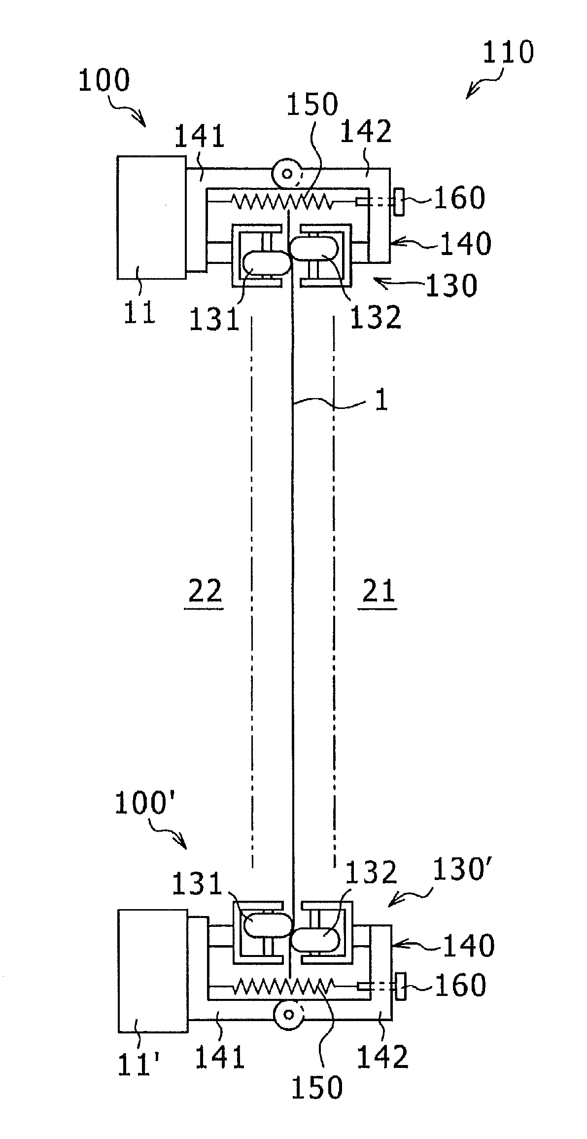
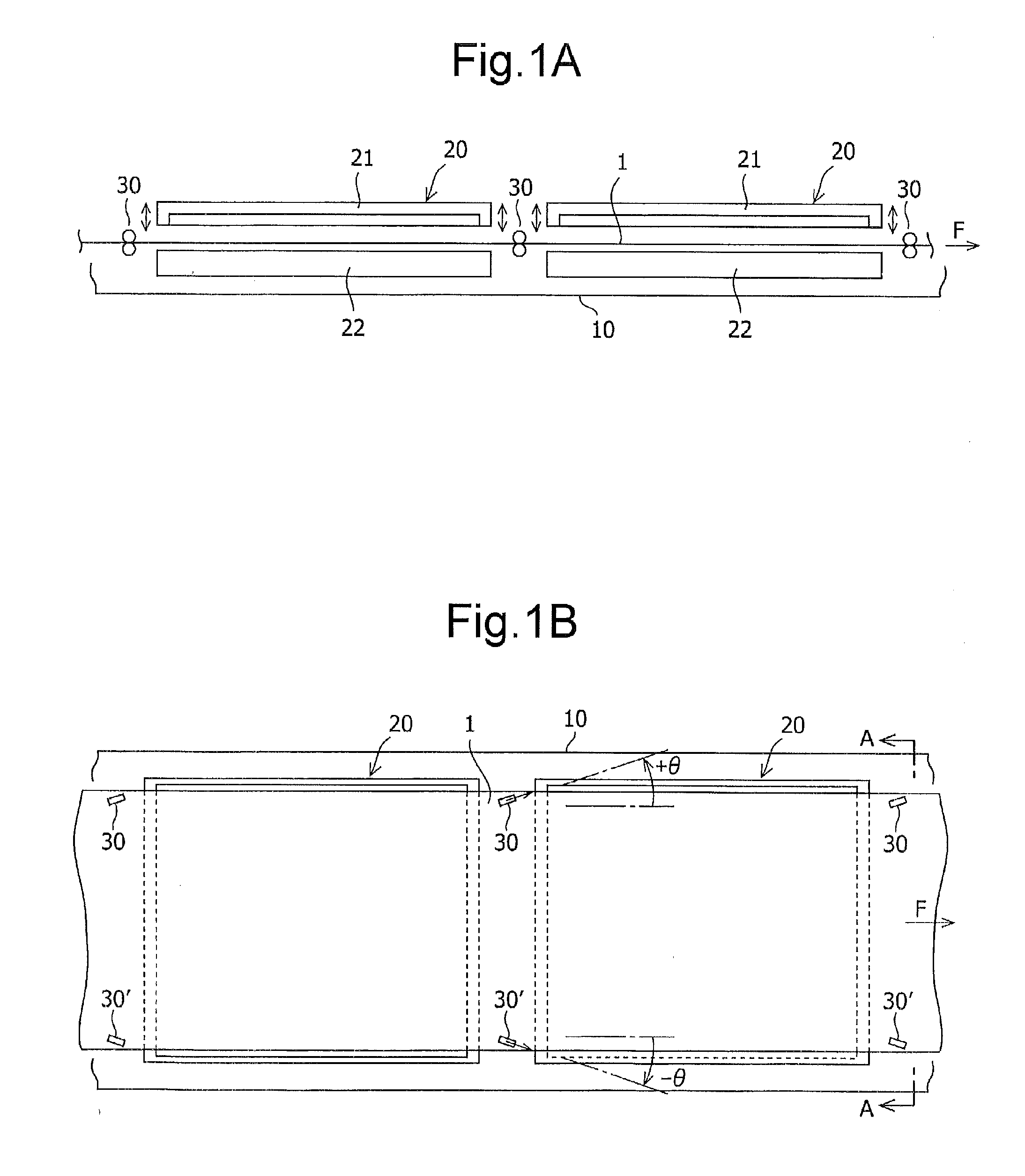
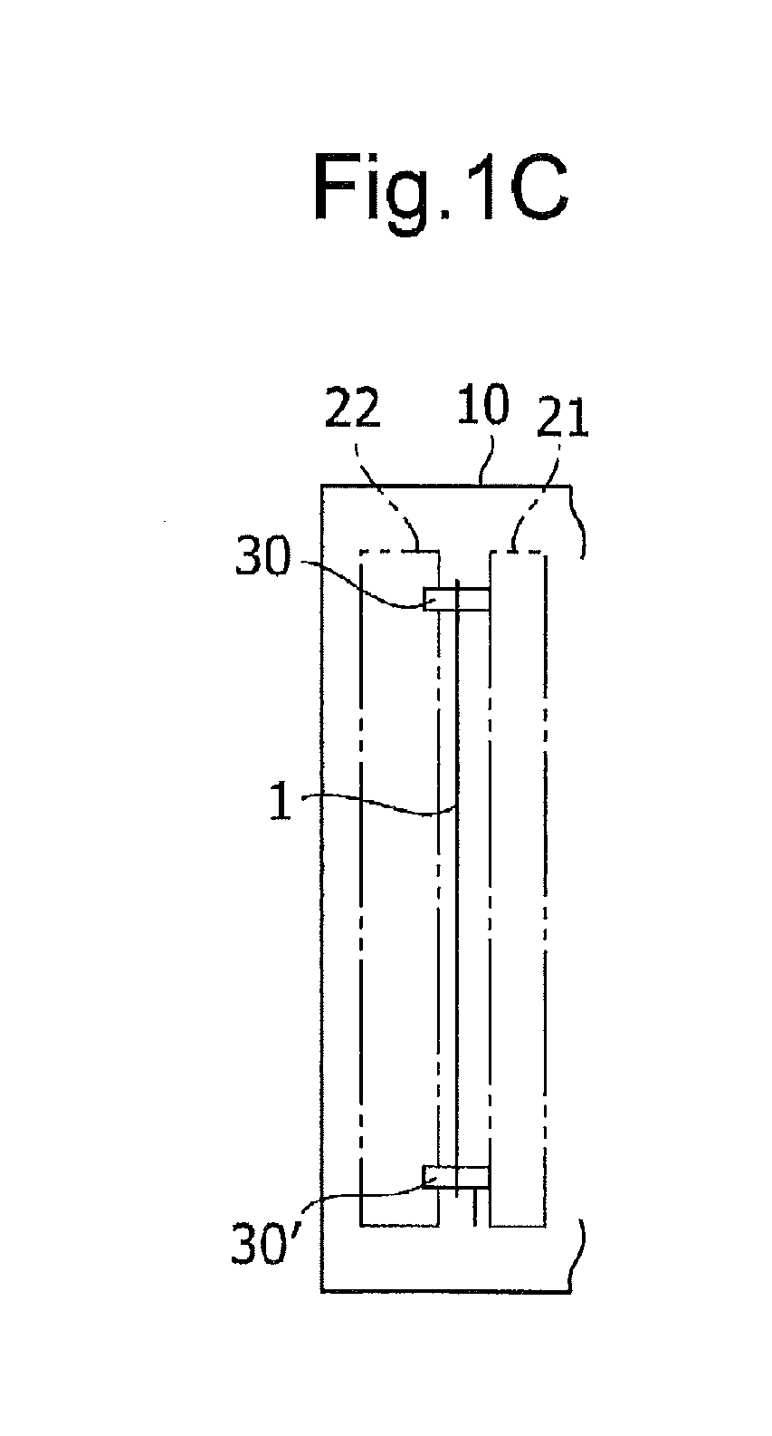
[0058]FIG. 2 is a front view as viewed from the upstream side in the direction of transport showing a substrate position control device 100 according to a first embodiment of the present invention. As partially shown in FIG. 1, a thin film laminate production device is provided with transport means within a vacuum chamber 10 maintained at a prescribed degree of vacuum that transports a band-shaped flexible substrate 1 (flexible film) in a horizontal direction with the direction of width thereof being the vertical direction, and laminates and forms a thin film on a surface of the flexible substrate 1 with a plurality of deposition units 20 arranged in a row along the transport path of the flexible substrate 1.

[0059]Rollers such as feed rollers and tension rollers that compose the transport means are arranged on the upstream side and downstream side of the deposition units in the direction of transport, and an unwinding roller and winding roller of the flexible substrate 1 are arrange...

second embodiment

[0076]Next, FIG. 8 is a front view as viewed from the upstream side in the direction of transport showing a substrate position control device 200 according to a second embodiment of the present invention, and FIG. 9 is an enlarged view of an essential portion thereof. As shown in the drawings, each of rollers 231 and 232 that compose a pair of clamping rollers 230 of the substrate position control device 200 of the second embodiment are tapered rollers having peripheral surfaces 231b and 232b respectively inclined relative to the axial direction, and in an operation state in which the pair of clamping rollers 230 are mutually contacted and separated, in contrast to a movable roller 232 being set so that a shaft 232a thereof is parallel to the transport surface, by setting a shaft 231a of a stationary roller 231 in a direction perpendicular to the shaft 232a of the movable roller 232, each of the peripheral surfaces 231b and 232b inclined relative to the axial direction are mutually ...

third embodiment

[0083]Next, FIG. 12 is a front view as viewed from the upstream side in the direction of transport showing a substrate position control device 300 according to a third embodiment of the present invention, and FIG. 13 is an enlarged view of an essential portion thereof. Each of rollers 331 and 332 that compose a pair of clamping rollers 330 of the substrate position control device 300 of the third embodiment have mutually different shapes. The stationary roller 331 is a cylindrical roller having a peripheral surface 331b parallel to the axial direction, and a shaft 332a is set in the vertical direction.

[0084]In contrast thereto, the movable roller 332 is a tapered roller having a peripheral surface 332b inclined relative to the axial direction, and in an operating state, the shaft 332a is set to have an inclination corresponding to the peripheral surface 332b so that the inclined peripheral surface 332b is pressed against the stationary roller 331 along a parallel peripheral surface ...


PUM

PropertyMeasurementUnit
temperatureaaaaaaaaaa
flexibleaaaaaaaaaa
pressing forceaaaaaaaaaa

Abstract

A flexible substrate position control device in a processing device, which transports a flexible substrate in a horizontal direction and in a vertical orientation and carries out processing of the substrate by processing units installed in a transport path of the substrate, is provided with a pair of clamping rollers that clamp an upper edge of the substrate, a support mechanism that rotatably supports the pair of clamping rollers, urging means for applying pressing force to the pair of clamping rollers, and adjusting means for adjusting the pressing force applied by the urging means. The pair of clamping rollers has an inclination, in which the direction of pressing relative to the clamping surface of the substrate is towards the edge of the substrate in the width direction, and is supported such that the rotating direction at the clamping surface is the same direction as the transport direction of the substrate.

Description

TECHNICAL FIELD[0001]The present invention relates to a flexible substrate position control device, and more particularly, to a control device that controls the position of a band-shaped flexible substrate in the width direction in a processing device that carries out processing such as film deposition while transporting the flexible substrate.BACKGROUND ART[0002]Although rigid substrates are normally used for the substrates of thin film laminates such as semiconductor thin films, there are also cases in which flexible substrates such as plastic films are used for the purpose of improving productivity and reducing costs by affording greater handling ease as a result of being lightweight and being able to be handled in rolls. For example, Patent Document 1 discloses a production device of a thin film laminate (thin film photoelectric conversion element) that laminates and forms a plurality of thin films of different properties on a flexible substrate and winds into a finished product...

Claims


Application Information

Patent Timeline
Patent Type & Authority Applications(United States)
IPC IPC(8): B32B38/18B65H20/02
CPCB65H20/02Y10T156/17B65H2301/321B65H2301/323B65H2301/325B65H2403/942B65H2404/144B65H2404/1451C23C14/562C23C16/545H01L21/67712H01L21/67721H01L21/6776H01L31/0392H01L31/206Y02E10/50B65H23/038H01L31/03926Y02P70/50
Inventor YOKOYAMA, SHOJIYAMADA, TAKANORIWADA, TAKENORI
Owner FUJI ELECTRIC CO LTD
Why Eureka
Try Eureka