Automatic wire arranging device of wire cutting machine and automatic wire arranging method thereof

An automatic wire arrangement and wire cutting machine technology, applied in electric processing equipment, metal processing equipment, electrode manufacturing, etc., can solve the problems of waste wire staying in the wire tube, need to push the waste wire and insufficient air force, so as to achieve positioning good effect

Inactive Publication Date: 2011-07-13
台湾线割科技股份有限公司
View PDF0 Cites 7 Cited by
  • Summary
  • Abstract
  • Description
  • Claims
  • Application Information

AI Technical Summary

Problems solved by technology

[0008] In order to solve the problems in the existing automatic wire arranging device of the wire cutting machine about the need to push the waste wire and the lack of air flow force, the waste wire deviation and the waste wire are stuck in the wire discharge pipe caused by the phenomenon, the present invention The purpose is to provide an automatic wire arranging device and an automatic wire arranging method of a wire cutting machine, which does not need to push waste wires, and uses the double force of air blowing and attraction to generate a stable traction flow field, which can effectively improve The problem that the waste wire deviates, cannot be sucked according to the predetermined route, and the waste wire is jammed and stays in the cable tube

Method used


Image

  • Automatic wire arranging device of wire cutting machine and automatic wire arranging method thereof
  • Automatic wire arranging device of wire cutting machine and automatic wire arranging method thereof
  • Automatic wire arranging device of wire cutting machine and automatic wire arranging method thereof

Examples


Embodiment Construction

[0077] In order to understand the technical features and practical effects of the present invention in detail, and to implement them according to the contents of the description, the preferred embodiment shown in the accompanying drawings will be described in detail as follows:

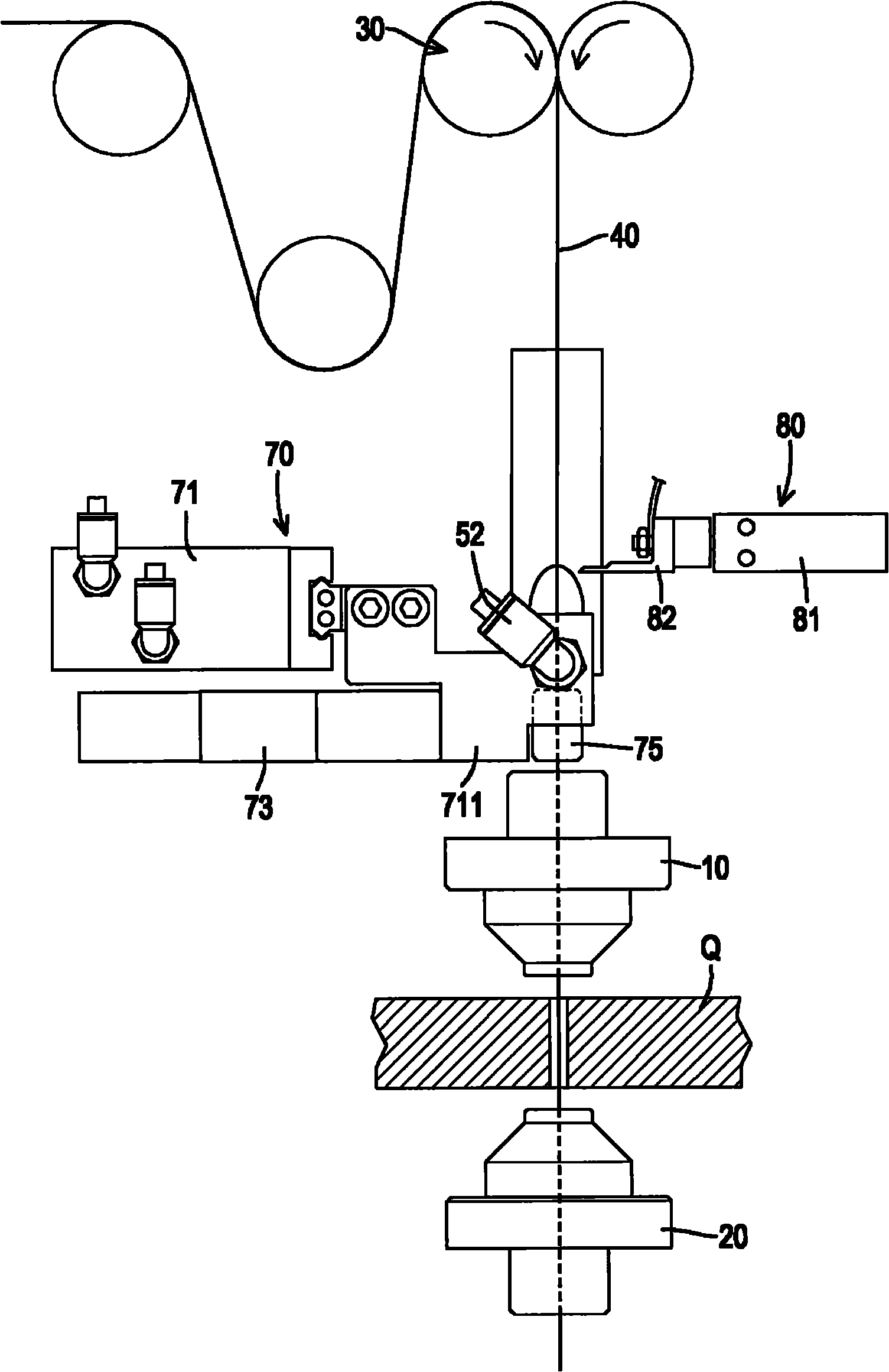
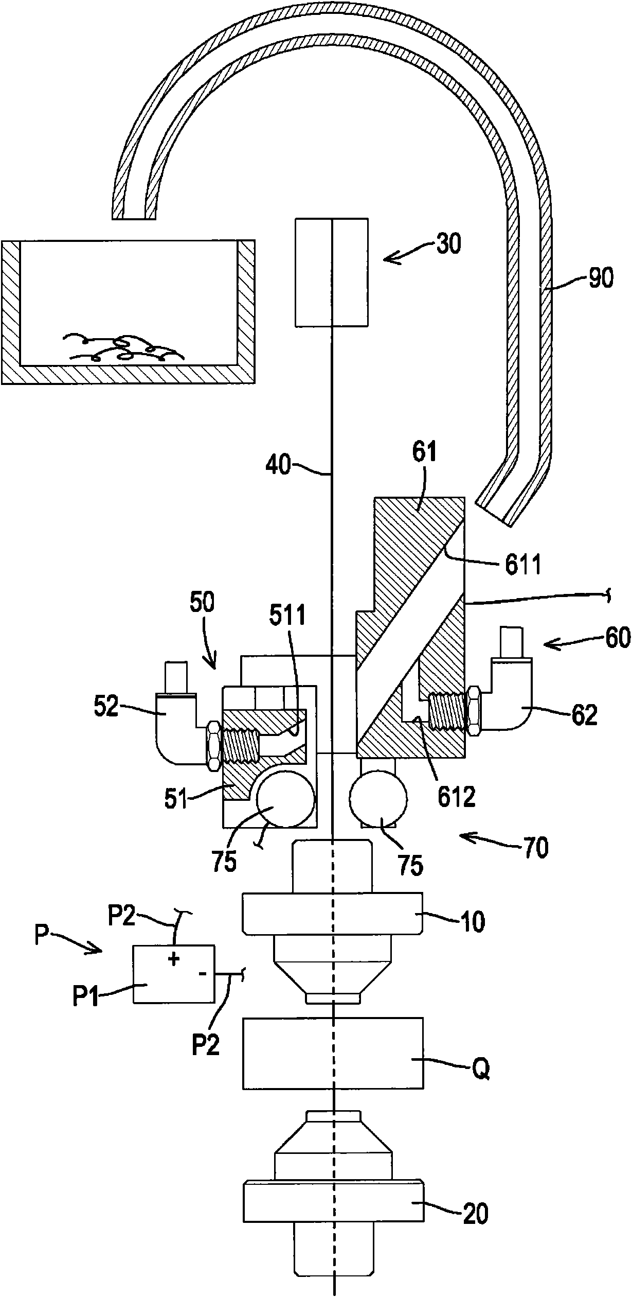
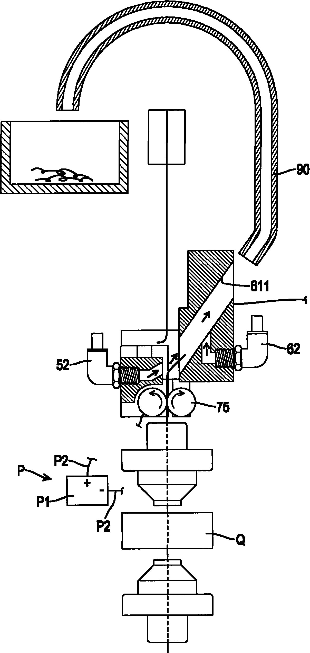
[0078] A preferred embodiment of the automatic wire arrangement device of a wire cutting machine provided by the present invention is installed on the wire cutting machine, such as figure 1 , figure 2 As shown, the wire cutting machine includes an upper positioning device 10, a lower positioning device 20, a wire outlet unit 30 and a wire body 40, wherein the wire body 40 is provided with a front side, a rear side, a left side and a On the right side, a metal workpiece Q is located between the upper positioning device 10 and the lower positioning device 20; the wire cutting machine belongs to the prior art, so its detailed structure and configuration relationship will not be repeated.

[0079] The ...


PUM


Abstract

The invention relates to an automatic wire arranging device of a wire cutting machine, which comprises a blowing unit, a sucking unit, a roller group, a wire fusing unit and a wire arranging tube, wherein the blowing unit generates a blowing air flow, and the sucking unit generates a sucking air flow. The invention also relates to the automatic wire arranging method of the automatic wire arranging device of the wire cutting machine. When the device and the method are used, a waste wire pushing action is not need, the blowing power and the sucking power of the air flows are used to generate a stable flow field to effectively solve the problem that the waste wire offsets and cannot be sucked in along a preset path, and whether the waste wire is removed completely can be judged according to the sensing signals of a sensing detection unit and a control system.

Description

technical field [0001] The invention relates to a component of a wire cutting machine for cutting metal, in particular to an automatic wire arranging device and an automatic wire arranging method of the wire cutting machine. Background technique [0002] Such as Figure 5 As shown, the current general existing wire cutting machine is provided with upper positioning device A, lower positioning device B, outlet unit C, wire take-up unit D and metal wire body E (such as copper wire, etc.); upper positioning device A and lower positioning device The device B is located above and below the metal workpiece F; the outlet unit C and the take-up unit D are respectively located above the upper positioning device A and below the lower positioning device B; after the metal wire body E is pulled out from the outlet unit C, the Pass through the upper positioning device A, the metal workpiece F and the lower positioning device B from the top to the bottom, and take up the metal wire body E...

Claims


Application Information

Patent Timeline
Patent Type & Authority Applications(China)
IPC IPC(8): B23H7/10
Inventor 杨世道
Owner 台湾线割科技股份有限公司
Why Eureka
Try Eureka