Floor drain for recycling heat of bathing waste water

A floor drain and waste water technology, applied in other non-combustion heat generation, waterway systems, heating devices, etc., can solve the problems of no deodorization and insect prevention, difficulty in descaling, scaling, etc., achieve good economic and social benefits, reduce preparation Effects of energy consumption and energy conservation

Inactive Publication Date: 2011-07-13
NORTH CHINA ELECTRIC POWER UNIV (BAODING)
View PDF5 Cites 10 Cited by
  • Summary
  • Abstract
  • Description
  • Claims
  • Application Information

AI Technical Summary

Problems solved by technology

After the bath water is used, it is directly drained through the drain pipe through the floor drain. The temperature of the bath waste water is generally around 35°C. The drained waste water contains a lot of heat, which is a serious waste of energy.
In order to solve the above problems, in the patent "A Floor Drain with Waste Hot Water Recovery Interface" (authorized publication number CN 1948645A), a floor drain with a waste hot water extraction path is described, but this technology has the following problems: 1. The floor drain cannot directly recover the heat of waste hot water, and needs to recover heat energy through a separate external waste heat recovery device; 2. The waste water itself cannot meet the pressure loss required to flow from the floor drain extraction channel to the waste heat recovery device, and needs to pass through sewage The pump is pressurized, which increases the investment and the consumption of high-quality electric energy; 3. Since the waste hot water is sewage, the waste hot water flows in the extraction channel for a long time, and it is easy to scale on the inner wall of the pipeline, and it is relatively difficult to remove the scale; 4. There is no deodorization and Anti-insect function

Method used


Image

  • Floor drain for recycling heat of bathing waste water
  • Floor drain for recycling heat of bathing waste water
  • Floor drain for recycling heat of bathing waste water

Examples


Embodiment Construction

[0018] The present invention will be further described below in conjunction with the accompanying drawings and embodiments.

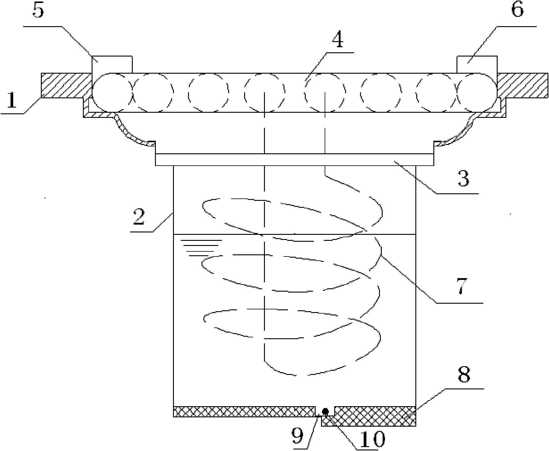
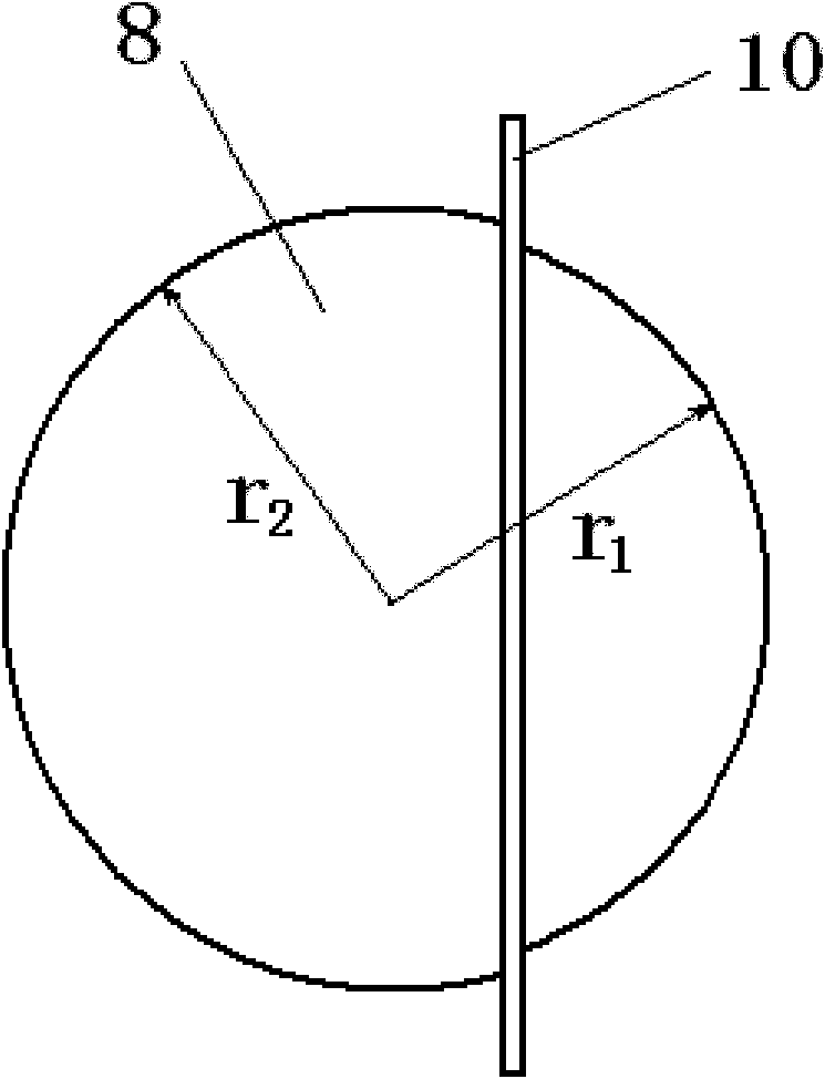
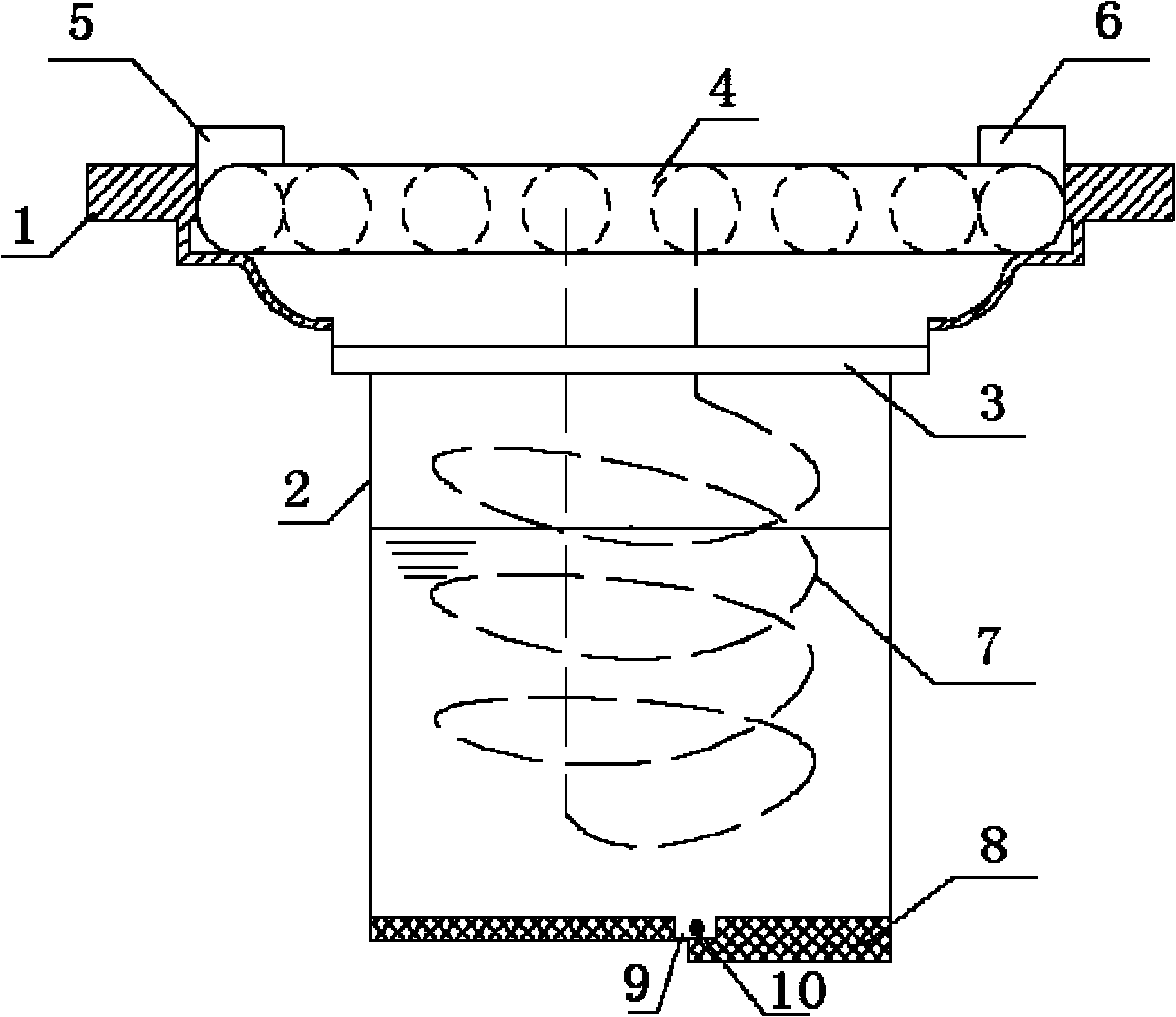
[0019] figure 1 Schematic diagram of embodiment structure for reclaiming bath waste water heat energy floor drain, as figure 1 As shown, the floor drain for recovering the heat energy of bathing wastewater is composed of a floor drain body 1, a floor drain core 2, a filter screen 3, an anti-odor and insect-proof device, and a waste water heat recovery device. On the steps, the anti-odor and anti-insect device is installed at the lower end of the floor drain core 2, the floor drain cover plate 4 of the waste water heat recovery device is placed on the rectangular steps of the floor drain main body 1, the heat exchange tube 7 is placed in the floor drain core 2, and the filter screen 3 is placed in the floor drain Core 2 on the circular steps.

[0020] The upper part of the floor drain main body 1 is a rectangular step, and the lower part is a bowl-shap...


PUM


Abstract

The invention discloses a floor drain for recycling heat of bathing waste water, which belongs to the field of energy-saving products. The floor drain for recycling heat of bathing waste water consists of a floor drain main body, a floor drain core, a filter screen, a deodorization and insect prevention device and a waste water heat recycling device, wherein a crimped rim edge at the upper end of the floor drain core is sleeved on a circular step of the floor drain main body; the deodorization and insect prevention device is arranged at the lower end of the floor drain core; a floor drain cover plate of the waste water heat recycling device is arranged in a rectangular step of the floor drain main body; a heat exchange tube is arranged in the floor drain core; the filter screen is arranged on the circular step of the floor drain core; during bathing, tap water exchanges heat with waste water through the floor drain cover plate and the heat exchange tube to recycle heat of bathing waste water; and when the waste water reaches a certain liquid level in the floor drain core, the deodorization and insect prevention device is opened under the action of gravity force to drain the waste water through a sewer. The floor drain has the advantages of simple structure, capabilities of fully recycling heat of bathing waste water, saving energy sources and preventing sewer odor from polluting indoor air, good economic and social benefits and suitability for household bathrooms.

Description

technical field [0001] The invention belongs to the field of energy-saving products, in particular to a floor drain for recovering the heat energy of bathing wastewater. Background technique [0002] With the improvement of people's living standards and the gradual development of good living habits, the consumption of hot water for bathing in families continues to increase. After the bathing water is used, it is directly drained through the drain pipe through the floor drain. The temperature of the bathing wastewater is generally around 35°C. The drained wastewater contains a lot of heat, which is a serious waste of energy. In order to solve the above problems, in the patent "A Floor Drain with Waste Hot Water Recovery Interface" (authorized publication number CN 1948645A), a floor drain with a waste hot water extraction path is described, but this technology has the following problems: 1. The floor drain cannot directly recover the heat of waste hot water, and needs to rec...

Claims


Application Information

Patent Timeline
Patent Type & Authority Applications(China)
IPC IPC(8): E03C1/282E03C1/288E03F5/042E03F7/06F24J3/00
Inventor 杨先亮时国华王江江张旭涛荆有印魏兵孙玮高月芬
Owner NORTH CHINA ELECTRIC POWER UNIV (BAODING)
Why Eureka
Try Eureka