Quick pipeline connecting method and joint using same
What is AI technical title?
AI technical title is built by Patsnap AI team. It summarizes the technical point description of the patent document.
A quick connection and pipeline technology, applied in the direction of mechanical equipment, couplings, etc., to avoid the reduction of sealing performance, improve reliability and tightness
Active Publication Date: 2011-07-13
LA CASA ANGELA HLDG
View PDF8 Cites 27 Cited by
Summary
Abstract
Description
Claims
Application Information
AI Technical Summary
This helps you quickly interpret patents by identifying the three key elements:
Problems solved by technology
Method used
Benefits of technology
Problems solved by technology
[0011] For this reason, the technical problem to be solved by the present invention is to solve a method that can not only make the insertion of the elastic tube body (such as the PEX tube body) relatively easy, but also ensure that the elastic tube body is not easy to insert after being inserted and fed with liquid pressurized and expanded. Loose, quick connection method for pipes with high airtightness and connection reliability and joint using the method
Method used
Image
Click on the blue label to locate the original text in one second.
Reading with bidirectional positioning of images and text.
Examples
Embodiment 1
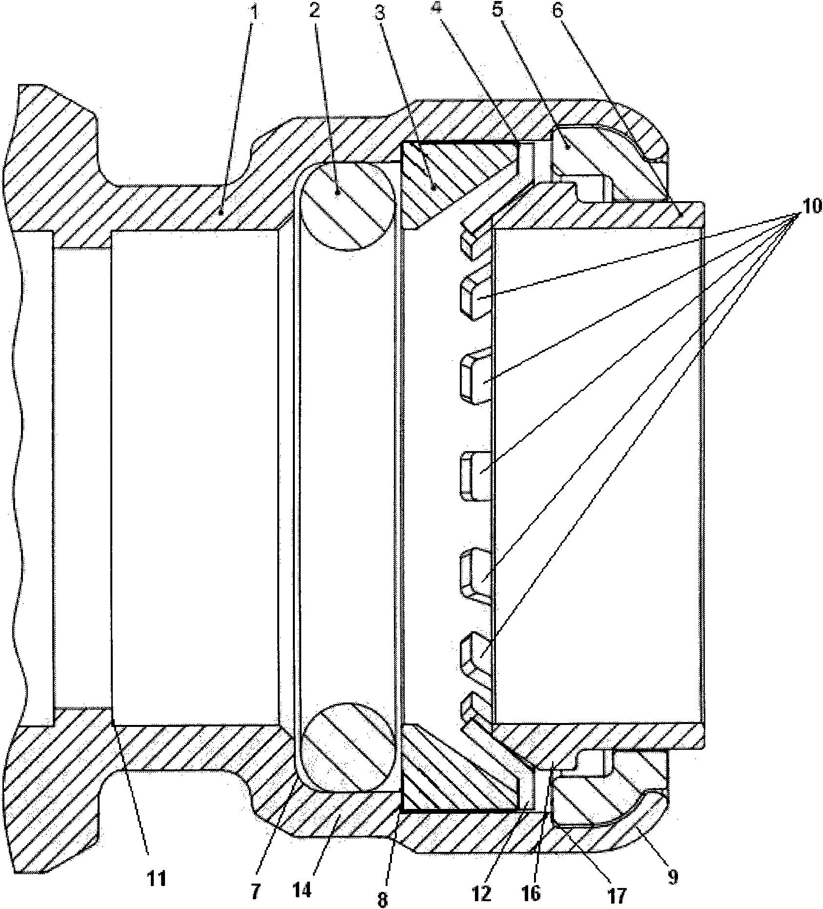
[0050] Such as figure 1 Piping quick connectors shown, including:
[0051] The joint body 1, the interior of the joint body 1 is sequentially arranged along the pipeline insertion direction (direction A):
[0052] Locking cap 5, used to prevent the inner parts from withdrawing;
[0053] The locking cap stopper part 9 is arranged on the pipe insertion end of the joint body, and is used to prevent the locking cap 5 from withdrawing;
[0054] Disassemble the ring 6 to release the locking of the pipeline;
[0055] The snap ring 4 has an annular elastic flange 12 and several latch teeth 10 arranged on the flange 12 for clamping the outer wall of the pipe 13;
[0056] The cone seat 3 is slidingly connected with the inner wall of the joint body 1, and is used to prevent the snap ring 4 from moving in the direction of pipe insertion;
[0057] The cone seat shoulder 8 is provided on the inner wall of the joint body 1, and is used to prevent the cone seat 3 from moving in the direct...
Embodiment 2
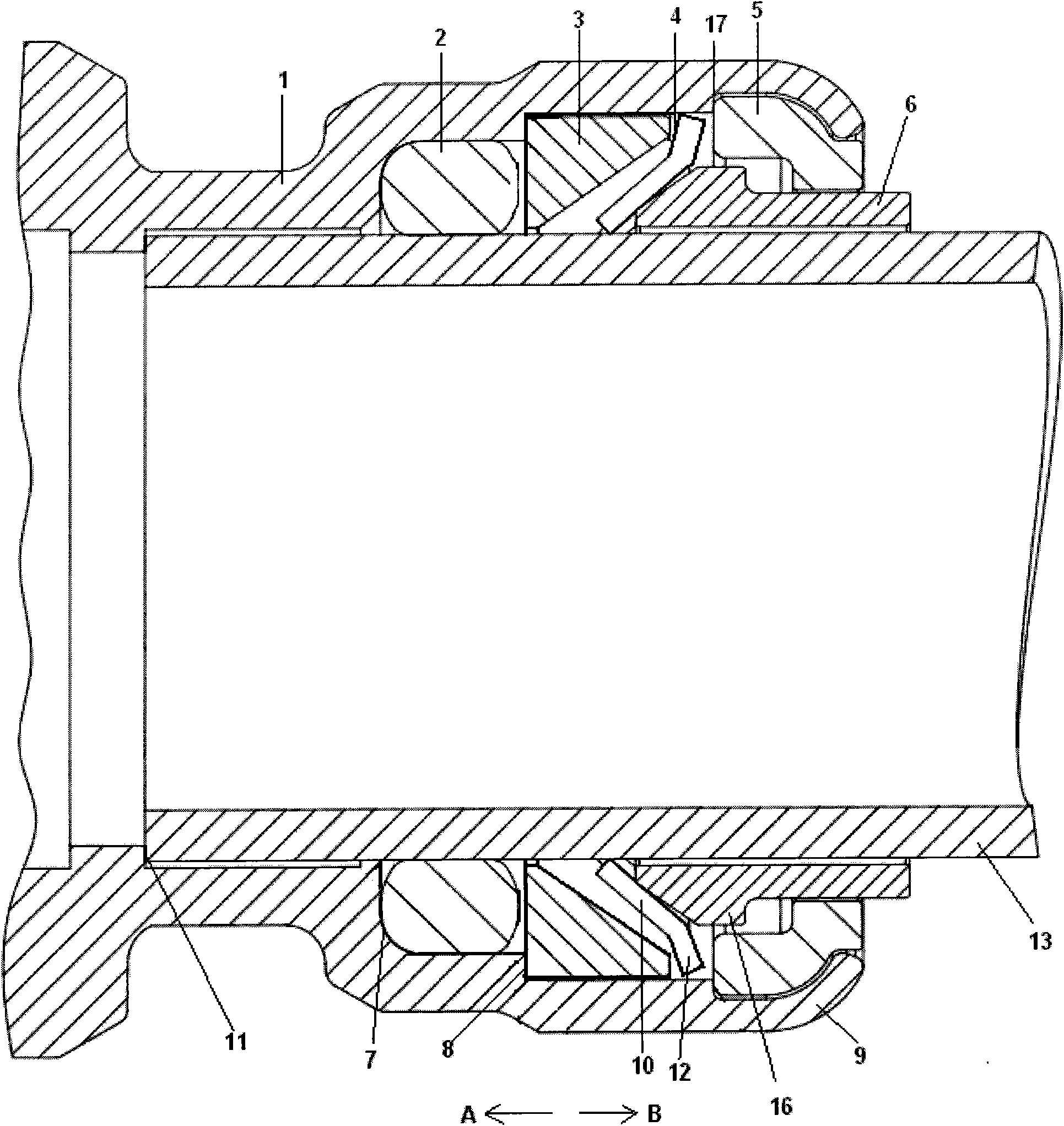
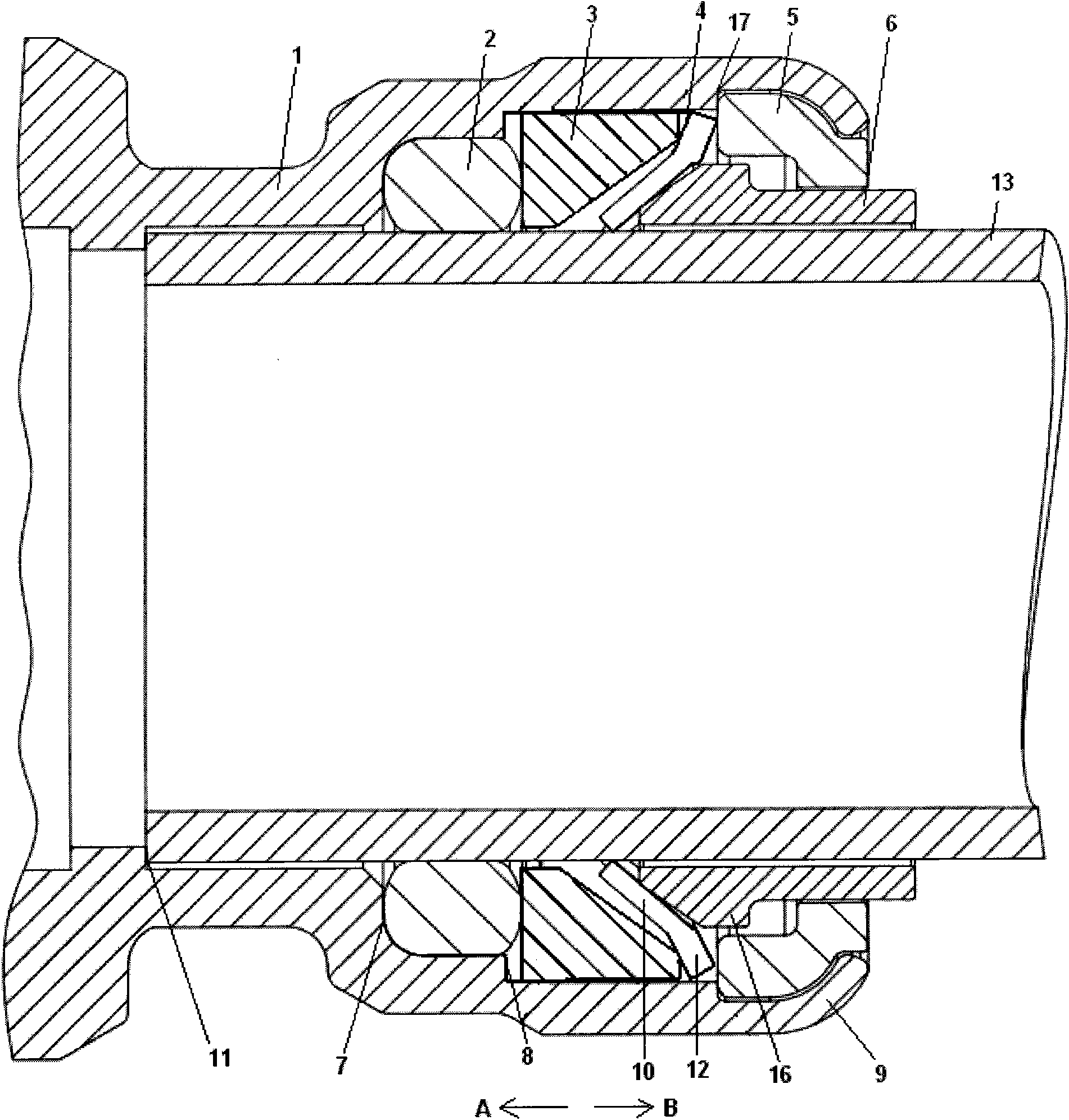
[0077] Such as Figure 4 Piping quick connectors shown, including:
[0078] The joint body 1, the interior of the joint body 1 is sequentially arranged along the pipeline insertion direction (direction A):
[0079] Locking cap 5, used to prevent the inner parts from withdrawing;
[0080] The locking cap stopper part 9 is arranged on the pipe insertion end of the joint body, and is used to prevent the locking cap from withdrawing;
[0081] Disassemble the ring 6 to release the locking of the pipeline;
[0082] The snap ring 4 has an annular elastic flange 12 and several latch teeth 10 arranged on the flange 12 for clamping the outer wall of the pipe 13;
[0083] The cone seat 3 is slidingly connected with the inner wall of the joint body 1, and is used to prevent the snap ring 4 from moving in the direction of pipe insertion;
[0084] The cone seat shoulder 8 is provided on the inner wall of the joint body 1, and is used to prevent the cone seat 3 from moving in the direction...
PUM
Abstract
The invention discloses a quick pipeline connecting method and a joint using the same. The joint comprises a joint body, wherein a clamping ring, a conical base and an O-shaped sealing ring are sequentially arranged inside the joint body along the pipeline insertion direction; when the pipeline is inserted into the joint, a flange arranged on the clamping ring is deflected; and when the pipeline expands under increased pressure after the introduction of a liquid, the O-shaped sealing ring expands axially under the action of pressure, and the clamping ring is driven to move along a direction opposite to the pipeline insertion direction by pushing the conical base to clamp the pipeline. The invention also discloses a quick pipeline joint adopting the quick connecting method. The joint has the advantages of capabilities of making an elastic pipe body (such as a PEX pipe body) easier to insert and ensuring that the elastic pipe body does not loosen easily after being inserted and expanded due to increased pressure caused by the introduction of the liquid, high air tightness and connecting reliability.
Description
technical field [0001] The invention relates to a method for connecting pipes, in particular to a method for quickly connecting fluid pipes such as water pipes and a joint using the method. Background technique [0002] Pipelines are essential infrastructure for industry. The pipeline connection device is an indispensable means of connection. [0003] At present, the well-known pipeline connections mainly include threaded connections and hot-melt connections (PP-R and PE pipes, etc.). The threaded connection is to use the joint and the pipe and its own internal and external threads for screw connection, and use the polytetrafluoroethyleneraw material tape as the sealing packing to seal; the hot-melt connection is to use electric heating to heat the connecting part of the pipe and the joint to a molten state , and then pressed against each other, so that the homogeneous materials on the contact surface melt into each other to connect and seal them. The above two connectio...
Claims
Application Information
Patent Timeline
Application Date:The date an application was filed.
Publication Date:The date a patent or application was officially published.
First Publication Date:The earliest publication date of a patent with the same application number.
Issue Date:Publication date of the patent grant document.
PCT Entry Date:The Entry date of PCT National Phase.
Estimated Expiry Date:The statutory expiry date of a patent right according to the Patent Law, and it is the longest term of protection that the patent right can achieve without the termination of the patent right due to other reasons(Term extension factor has been taken into account ).
Invalid Date:Actual expiry date is based on effective date or publication date of legal transaction data of invalid patent.

