Flywheel simulator based on FPGA

A simulator and flywheel technology, applied in the field of flywheel simulation, can solve the problems of low accuracy of output results and slow operation speed, and achieve the effects of shortening operation time, improving speed and accuracy, and simplifying hardware circuits

Inactive Publication Date: 2012-10-17
HARBIN INST OF TECH
View PDF0 Cites 0 Cited by
  • Summary
  • Abstract
  • Description
  • Claims
  • Application Information

AI Technical Summary

Problems solved by technology

[0019] In order to solve the problem of slow operation speed and low precision of the output results realized by the existing digital signal processor DSP, the present invention proposes a flywheel simulator based on FPGA

Method used


Image

  • Flywheel simulator based on FPGA
  • Flywheel simulator based on FPGA
  • Flywheel simulator based on FPGA

Examples


specific Embodiment approach 1

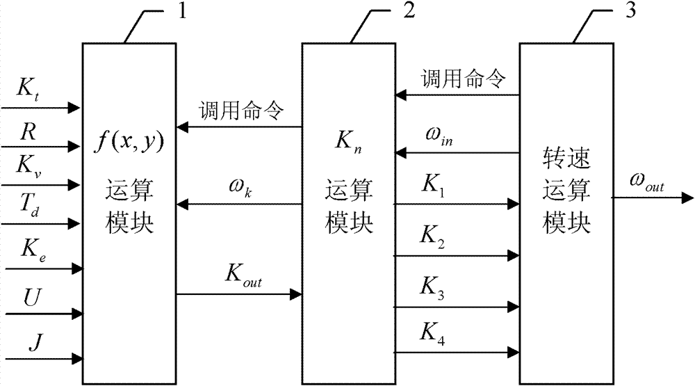
[0034] Specific embodiment one: a kind of FPGA-based flywheel simulator described in the present embodiment adopts FPGA to realize, and comprises three computing modules in the described FPGA, and described three computing modules are respectively f (x, y) computing module 1 、K n Operation module 2 and rotational speed operation module 3;

[0035] The rotational speed operation module 3 is used to send a calling command to K n The operation module 2 starts a Runge-Kutta iterative operation, and is also used to calculate the result information of this iterative operation according to the received parameter information, and use the iterative result information of this time as the last iterative result ω in Send to send K n The computing module 2, meanwhile, also uses the information of the iterative result of this iteration as the speed result ω of the flywheel model out output;

[0036] The K n The operation module 2 is used to send the call command to the f(x, y) operatio...

specific Embodiment approach 2

[0038]Specific embodiment two: this embodiment is to further limit the structure of the rotating speed calculation module 3 in a kind of FPGA-based flywheel simulator described in the specific embodiment one, and the rotating speed computing module 3 described in the present embodiment is composed of the fifth Adder 16, the sixth adder 17, the seventh adder 19, the eighth adder 21, the fifth multiplier 18 and the sixth multiplier 20 are composed of K n Input K of operation module 2 1 and K 2 As the input information of the fifth adder 16, the output sum information of the fifth adder 16 is given to the seventh adder 19; by K n Input K of operation module 2 3 and K 4 As the input information of the sixth adder 17, the sixth adder 17 outputs the sum information to the fifth multiplier 18, and the fifth multiplier 18 multiplies the input information by 2 and then outputs the multiplication result information to the seventh adder 19, the seventh adder 19 outputs the sum result...

specific Embodiment approach 3

[0040] Specific embodiment three: this embodiment is the K in a kind of FPGA-based flywheel simulator described in specific embodiment one n For further limitations on the structure of the computing module 2, the K described in this embodiment n Computing module 2 is made up of selector 15, the 4th multiplier 13 and the 4th adder 14, and described 4th multiplier 13 receives the output result K of f(x, y) computing module 1 out , DT is used as the input information of the fourth multiplier 13, the fourth multiplier 13 outputs the multiplication result to the fourth adder 14, and the output result ω of the last iteration output by the rotational speed calculation module 3 in At the same time as the input information of the fourth adder 14 and the fourth selector 15, the fourth adder 14 outputs the sum information to the selector 15, and the selection result information ω output by the selector 15 k as K n The output information of the operation module 2 is given to the f(x, y)...


PUM


Abstract

The invention discloses a flywheel simulator based on FPGA (Field Programmable Gata Array), which relates to a flywheel simulation technology in the technical field of satellite simulation, and solves the problem of low computing speed and low accuracy of output result in the simulation implemented by the prior DSP (Digital Signal Processor). In the flywheel simulator based on the FPGA, a VerilogHDL language is used, an IP core is used as a basic computing unit for multiplication, division, addition and the like, and three computing modules are created according to a solving process of a Four--Runge-Kutta method, wherein a revolving speed computing module is used for transmitting a call instruction to a Kn computiong module to start a Runge-Kutta iterative operation once and obtain the revolving speed result Omega out; the Kn computing module is used for continuously transmitting the call instruction to f(x, y) after receiving the call instruction from the revolving speed computing module so as to obtain four parameters K1, K2, K3 and K4; and the f(x, y) computing module is used for computing a parameter Kn after receiving the call instruction from the Kn computing module. The flywheel simulator provided by the invention is rapid in response and high in accuracy of output result.

Description

technical field [0001] The invention is an application technology of FPGA, and specifically relates to the flywheel simulation technology in the field of satellite simulation technology. technical background [0002] The satellite attitude control system includes three components: attitude sensor, attitude controller and actuator, which are used to complete the attitude control of the satellite. The attitude sensor (such as the sun sensor, star sensor, earth sensor, etc.) is used to obtain the current attitude information of the satellite; the attitude controller is used to analyze and process the current attitude information obtained by the attitude sensor, and generate feedback to the actuator according to the demand. The control command; the actuator (such as flywheel, magnetic torque device, thruster, etc.) is used to make corresponding actions according to the control command generated by the attitude controller to adjust the satellite attitude. The connection relation...

Claims


Application Information

Patent Timeline
Patent Type & Authority Patents(China)
IPC IPC(8): G05D17/02
Inventor 赵光权彭宇刘大同马飞王少军庞业勇
Owner HARBIN INST OF TECH
Why Eureka
Try Eureka