Gas introduction method for reinforced gas-liquid mass transfer and device

A technology of gas introduction and gas enhancement, which is applied in the field of gas-liquid mixing and mass transfer, can solve the problems of increasing the specific surface area of ​​gas-liquid contact, improving the effect of gas-liquid mass transfer, and affecting the gas utilization rate, etc., to achieve enhanced mutual permeability , Easy to install, reduce the effect of cleaning investment

Active Publication Date: 2013-06-12
河北广盛源科技有限公司
View PDF3 Cites 0 Cited by
  • Summary
  • Abstract
  • Description
  • Claims
  • Application Information

AI Technical Summary

Problems solved by technology

At present, the commonly used method is to install various forms of gas distribution devices with the function of refining and discharging bubbles at the end of the inlet pipe that passes into the reaction liquid, such as multi-outlet nozzles, porous ring pipes, sintered metal mesh, and microporous membranes. And various forms of aerators, etc. Compared with directly passing gas into the reaction liquid through the intake pipeline, the above-mentioned gas distribution devices can increase the specific surface area of ​​gas-liquid contact to a certain extent, and play a role in improving the gas-liquid mass transfer conditions. It has a certain promotion effect, but because of its working principle and the functions it realizes are only limited to the refinement of the discharged bubbles, and the phenomenon of bubble coalescence is serious after leaving the gas distribution device, it is difficult to transfer the gas-liquid mass transfer during the reaction process. The effect is improved to a more ideal level, and the gas utilization rate is greatly affected

Method used


Image

  • Gas introduction method for reinforced gas-liquid mass transfer and device
  • Gas introduction method for reinforced gas-liquid mass transfer and device
  • Gas introduction method for reinforced gas-liquid mass transfer and device

Examples


Embodiment 1

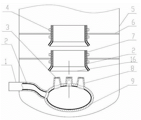
[0032] Embodiment 1: attached figure 1 It is a structural diagram of the built-in gas introduction device of the present invention, which is installed below the liquid level in the gas-liquid reactor 5, and six gas nozzles 8 correspond to a group of coaxially arranged two-stage circulation mixing cylinders arranged behind the gas nozzles 8 Example at 7 o'clock.

[0033] Present embodiment 1 comprises the inlet pipe 1 that stretches into below the liquid level in the gas-liquid reactor 5 and the air distribution bag 9 that is installed at the end of the air inlet pipe 1, and the inner wall of the air inlet pipe 1 and the air distribution bag 9 is coated with tourmaline or other An anion coating 2 refined from rare earth stone materials is connected to 6 gas nozzles 8 integrated with a fluid ultrasonic whistle 3 on the gas distribution bag 9. The structure of the gas nozzle 8 is as follows: figure 1 As shown, its main body is a tubular with a circular cross-section and a taper,...

Embodiment 2

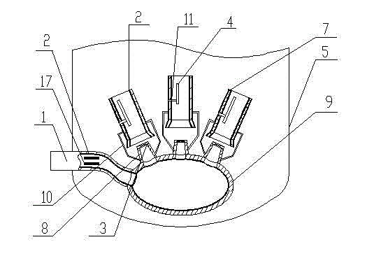
[0034] Embodiment 2: attached figure 2 It is another built-in gas introduction device of the present invention, which is installed below the liquid level in the gas-liquid reactor 5, and is an embodiment in which each gas nozzle 8 corresponds to a single-stage circulating mixing cylinder 7 arranged thereafter.

[0035]Its structure comprises the inlet pipe 1 that stretches into the gas-liquid reactor 5 below the liquid level and the gas distribution bag 9 installed at the end of the inlet pipe 1, and the multi-layer plate-shaped packing 17 is set in the air inlet pipe 1, and the packing 17 includes several The gas flows to the parallel packing plates. The outer surface of each layer of packing plates is coated with negative ion coating refined from tourmaline or other rare earth stones. There is a certain distance between each layer of packing plates as gas channels, and other packing plates can also be used. shape filler. Six gas nozzles 8 integrated with the fluid ultrason...

Embodiment 3

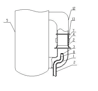
[0036] Embodiment 3: Attach image 3 It is an external gas introduction device of the present invention, installed on the external circulation pipeline 12 outside the gas-liquid reactor 5, and is an embodiment in which one gas nozzle 8 corresponds to one single-stage circulation mixing cylinder 7 arranged behind it.

[0037] Its structure includes the air inlet pipe 1 arranged outside the gas-liquid reactor 5 and extending into the bottom of the external circulation pipe 12 arranged outside the gas-liquid reactor 5, and the inner wall of the air inlet pipe 1 is coated with tourmaline or other rare earth stone refined The negative ion coating 2 that forms, connects the gas nozzle 8 of an integrated fluid ultrasonic whistle 3 at the air intake pipe 1 end, and the structure of the gas nozzle 8 and the fluid ultrasonic whistle 3 is identical with that in the above-mentioned embodiment 1. The circulation mixing cylinder 7 integrated with the ultrasonic transducer 4 has a single-sta...


PUM


Abstract

The invention provides a gas introduction method for reinforced gas-liquid mass transfer. The key technology comprises that: a gas with pressure enters a gas inlet pipe of a gas-liquid reactor and a gas distribution pocket at the tail end of the gas inlet pipe, and the gas is rubbed with negative ion powder coatings coated on the inner walls of the gas inlet pipe and the gas distribution pocket or a filler coated with a negative ion powder coating on the outer surface in the gas inlet pipe in the flowing process of the gas, so that the gas is excited and a large amount of negative ions are accumulated; and the gas rich in the negative ions is jetted from a gas nozzle of an integrated fluid ultrasound whistle led out from the gas inlet pipe or the gas distribution pocket, and the ultrasonic wave produced when the gas passes through the fluid ultrasound whistle enters the surrounding reaction liquid and drives the surrounding reaction liquid to jointly enter a circular mixing cylinder so as to finish gas dispersion of ultrasonic wave and negative ion double reinforced mass transfer, wherein the circular mixing cylinder is arranged in back of the nozzle, the inner and outer walls of the circular mixing cylinder are coated with negative ion powder coatings, and an ultrasonic transducer is arranged on the outer wall or in the cavity of the circular mixing cylinder.

Description

technical field [0001] The invention relates to a gas introduction method and device for enhancing gas-liquid mass transfer, especially suitable for gas-liquid reactors, and belongs to the technical field of gas-liquid mixing and mass transfer. Background technique [0002] In many gas-liquid reactions that use liquid as the continuous phase and gas as the dispersed phase, such as hydrogenation, chlorination, ammoniation, oxidation, aerobic biological fermentation, etc., most of them need to introduce a certain pressure of gas into the reactor. In the liquid, in order to achieve good gas-liquid mixing and mass transfer. At present, the commonly used method is to install various forms of gas distribution devices with the function of refining and discharging bubbles at the end of the inlet pipe that passes into the reaction liquid, such as multi-outlet nozzles, porous ring pipes, metal sintered meshes, and microporous membranes. And various forms of aeration heads, etc. Compa...

Claims


Application Information

Patent Timeline
Patent Type & Authority Patents(China)
IPC IPC(8): B01J19/08B01J19/10
Inventor 方民
Owner 河北广盛源科技有限公司
Why Eureka
Try Eureka