Method for processing crankshaft of multiaxial warp knitting machine

A crankshaft processing and warp knitting machine technology, applied in the field of warp knitting machines, can solve the problems of affecting the included angle, large position error, large end face error, etc., and achieve the effect of ensuring tolerance requirements

Inactive Publication Date: 2011-07-20
沈阳气体压缩机制造有限公司
View PDF3 Cites 9 Cited by
  • Summary
  • Abstract
  • Description
  • Claims
  • Application Information

AI Technical Summary

Problems solved by technology

The large error of the end face affects the straightness of the entire slender crankshaft and the coaxiality of each main shaft diameter
The position error between the three φ12 pin holes is large, which will affect the assembly of the three φ12 positioning pin screws
If the position error between the three φ12 pin holes and the first connecting rod diameter is large, it will affect the angle between the connecting rod diameter and the main shaft diameter of the adjacent small crankshaft, thus affecting the quality of the fabric
[0004] The common process flow of crankshaft processing with general precision requirements is as follows: drilling→rough turning→quenching and tempering→drilling→finish turning→dimple milling→rough grinding→high frequency quenching→finish grinding→drilling. The eccentricity tolerance requirements of the diameter and the main shaft diameter

Method used


Image

  • Method for processing crankshaft of multiaxial warp knitting machine
  • Method for processing crankshaft of multiaxial warp knitting machine
  • Method for processing crankshaft of multiaxial warp knitting machine

Examples


Embodiment Construction

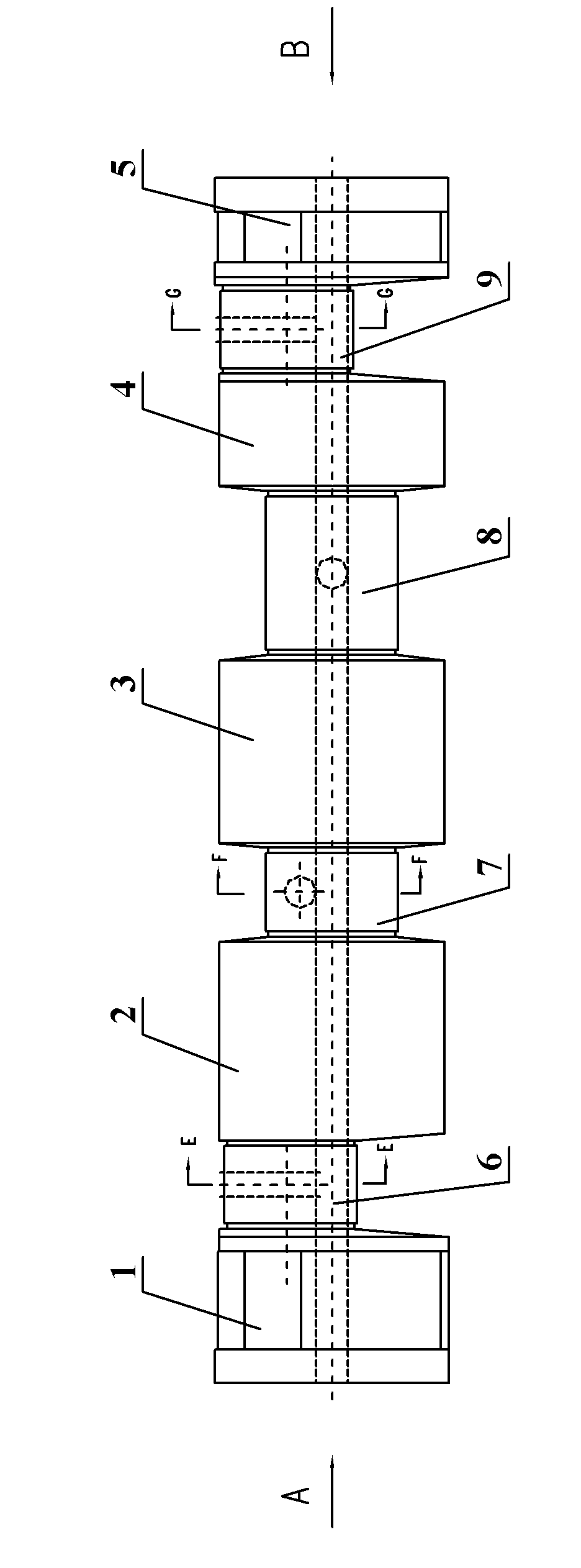
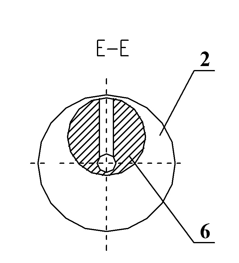
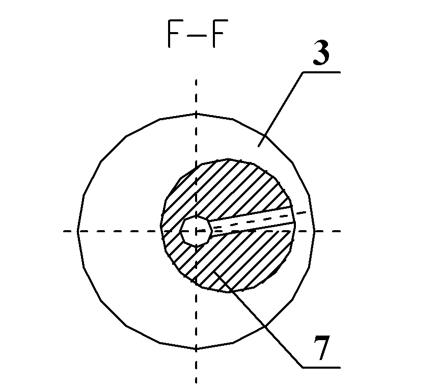
[0028] Such as Figure 1 to Figure 6 The shown schematic diagram of the crankshaft structure for a multi-axial warp knitting machine, the crankshaft includes a main shaft diameter and a connecting rod diameter, the connecting rod diameter is arranged between the main shaft diameters, and the connecting rod diameter in the crankshaft includes the connecting rod diameters 6, 7, 8 and 9, the main shaft diameter includes main shaft diameters 1, 2, 3, 4 and 5, wherein three pin holes are respectively set on main shaft diameter 1 and main shaft diameter 5, and pin holes 11, 12 and 13 are set on main shaft diameter 1, The main shaft diameter 5 is provided with pin holes 51 , 52 and 53 . When using the crankshaft, multiple crankshafts can be connected together for use through the pin holes. In the processing process, the tolerance of the eccentricity between the diameter of the connecting rod and the diameter of the main shaft is ±0.0055mm, and the tolerance of the included angle is ...


PUM

PropertyMeasurementUnit
diameteraaaaaaaaaa

Abstract

The embodiment of the invention discloses a method for processing a crankshaft of a multiaxial warp knitting machine. The crankshaft comprises a spindle diameter and a connecting rod diameter. The connecting rod diameter is connected with the spindle diameter. The method comprises the following steps of: step A: processing a raw material through the steps of drilling a first center hole, roughly turning, hardening and tempering, and fine turning an outer diameter to obtain a polished shaft; step B: respectively drilling a second center hole of the crankshaft and a third center hole of the connecting rod diameter at the opposite positions at both ends of the polished shaft, drilling a process positioning hole at the position at a distance of 20mm from the first center hole, carrying out fine turning on the spindle diameter and the connecting rod diameter according to the process positioning hole, the second center hole and the third center hole, and carrying out milling and rough grinding to obtain a semi-finished product; and step C: carrying out high-frequency quenching on the semi-finished product, drilling and reaming pin holes at both ends of the semi-finished product and carrying out fine grinding processing to obtain a finished product. In the embodiment of the invention, when the outer diameter, the spindle diameter and the connecting rod diameter are subjected to fine turning, positioning is carried out through the process positioning hole and the respective center holes, so that when the outer diameter, the spindle diameter and the connecting rod diameter are processed, the requirement on a tolerance of the eccentricity of the connecting rod diameter and the spindle diameter of the crankshaft can be guaranteed.

Description

technical field [0001] The invention relates to the field of warp knitting machines, in particular to a crankshaft processing method of a multiaxial warp knitting machine. Background technique [0002] Multiaxial warp knitted fabric is a new type of fabric structure developed in the late 1980s. In addition to the stretched yarns in the warp and weft directions to bear external loads, this fabric can also be configured with up to seven groups of parallel yarn sheets adjusted to different orientations according to needs, and these fibers are fixed by the coil system. The machine tool for producing multi-axial warp knitted fabrics - multi-axial warp knitting machine, the structure of the domestic traditional machine is cam drive. At the end of the 20th century, Karl Mayer of Germany took the lead in changing the cam drive to crankshaft drive. It not only reduces the overall size of the machine, but also increases the transmission speed, thereby increasing the output of knitte...

Claims


Application Information

Patent Timeline
Patent Type & Authority Applications(China)
IPC IPC(8): B23P15/00
Inventor 董树林席行宪
Owner 沈阳气体压缩机制造有限公司
Why Eureka
Try Eureka