Pump dispenser and method of assembly of such a dispenser

A dispenser, container technology, used in packaging, spray devices, transportation and packaging, etc., to solve problems such as product extrusion

Active Publication Date: 2011-07-20
RIEKE
View PDF10 Cites 11 Cited by
  • Summary
  • Abstract
  • Description
  • Claims
  • Application Information

AI Technical Summary

Problems solved by technology

If the product is overfilled (some variation is unavoidable in practice), there is a risk of product being squeezed out through the gap, which must be avoided

Method used


Image

  • Pump dispenser and method of assembly of such a dispenser
  • Pump dispenser and method of assembly of such a dispenser
  • Pump dispenser and method of assembly of such a dispenser

Examples


Embodiment Construction

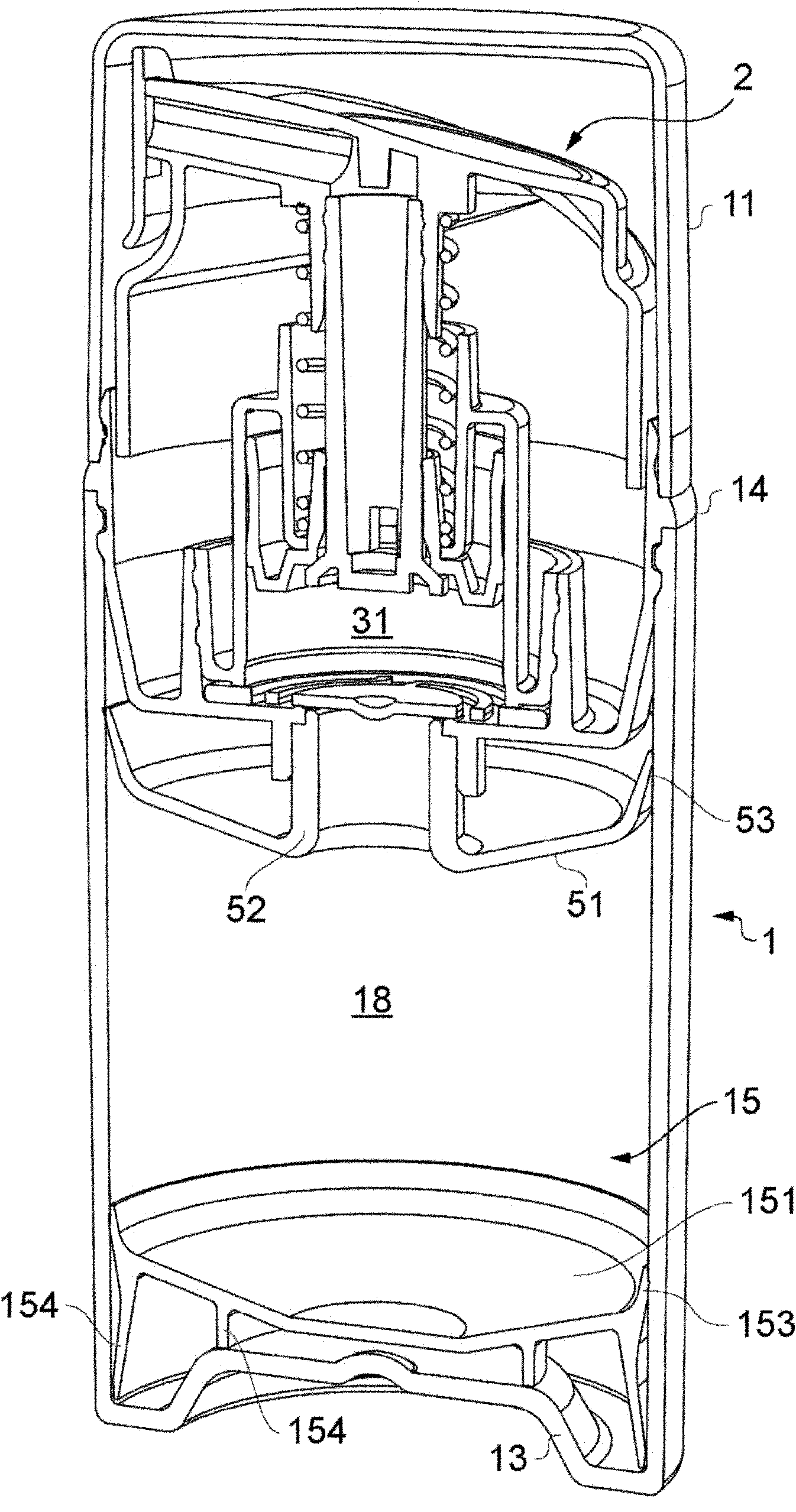
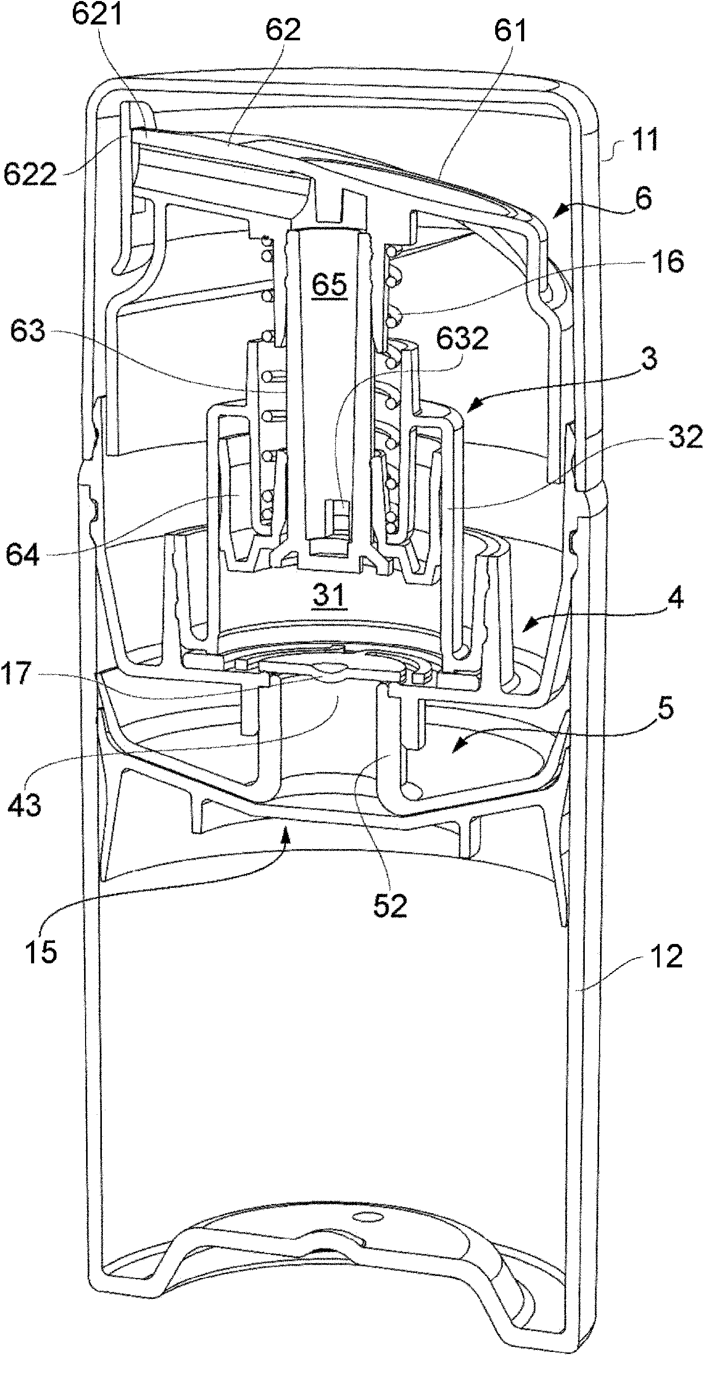
[0049] refer to Figures 1 to 3 , the hand-operated dispenser includes a cylindrical container 1 , a pump module 2 installed in a circular neck opening 14 of the container and a cap 11 covering the pump module 2 . The main components of the pump module 2 are the pump plunger 6 , the pump body 3 , the pump body base or adapter 4 and the accumulation insert 5 . See figure 2 .

[0050] A circular follower piston 15 operates in the interior space 18 of the container 1 . figure 1 shows the initial position when the container is full, figure 2 is the final position when all possible products have been allocated. The follower piston 15 has a circular sealing lip 153 , a disc-shaped central web 151 and an annular support rib 154 which initially supports the central web above the container base 13 .

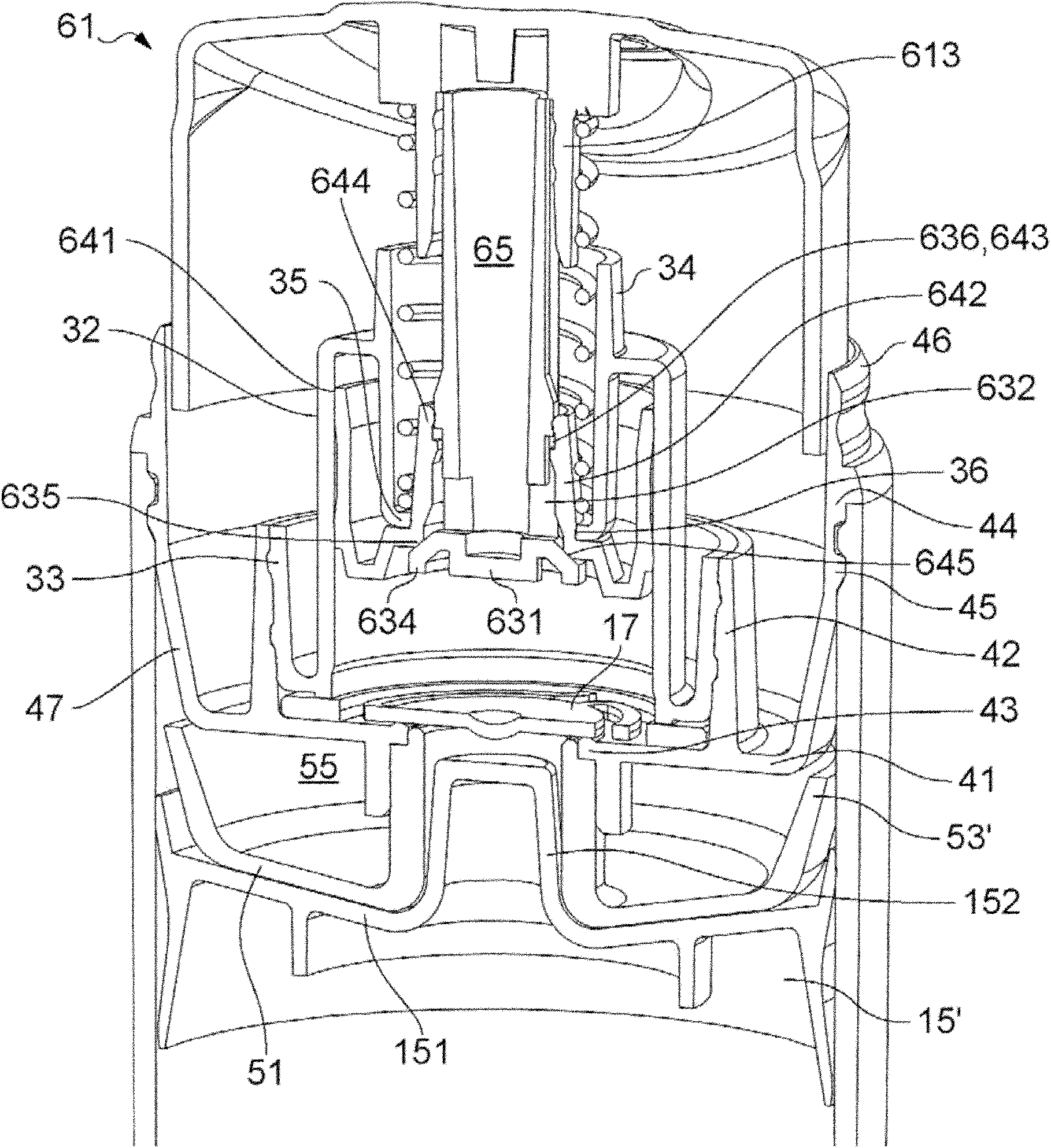
[0051] In a generally conventional manner, manual depression of the plunger 6 against the pump spring 16 reduces the volume of the pump chamber 31 defined by the cylinder 32 of the...


PUM


Abstract

The disclosure relates to a pump dispenser and a method of assembly of such a dispenser, in which the container interior reduces its volume progressively as product is dispensed to avoid air contact with the product. One aim is to prevent any air in the container space above the product from reaching the pump inlet, and thereby possibly reducing a dispensed dose without the user being aware. To trap any such air and keep it away from the inlet throughout use of the dispenser, an air trap member (5) having a downwardly-convex dish form is provided below the floor of the dispenser module around the inlet, to guide any such air away from the inlet and to the periphery. At the periphery a steeply-sloping peripheral portion forms a retaining lip (53), which may make flexible wiping contact with the container wall interior, allowing air past on assembly of the dispenser. A central tubular formation (52) of the trap member (5) separates the trapped air from the inlet, and can be used to plug the trap member into the inlet. A sliding follower piston (15) may have an upward central boss (152) shaped to fit into the tubular formation (52) of the trap member (5) to maximise expulsion of product.

Description

technical field [0001] The present invention relates to a pump dispenser comprising a container and a dispenser pump for dispensing a fluid product from the container. Background technique [0002] Pump dispensers with a dispenser pump mounted on a product container are known for dispensing fluid products (liquids, ointments, pastes) such as cosmetics and pharmaceuticals. [0003] Usually the pump body includes a cylinder as a stationary part. A piston may be on an inner end of a plunger, the manually engageable outer end of which protrudes from an opening in the body and is reciprocable during a pump stroke to vary the volume of the pump chamber. Thus, dispenser pumps are typically of the type in which the pump chamber is defined between a piston and a cylinder. Liquid product enters the pump chamber via a valved inlet and leaves the pump chamber via an outlet, usually also valved, leading along an outlet channel to a discharge opening. Commonly used valves include ball ...

Claims


Application Information

Patent Timeline
Patent Type & Authority Applications(China)
IPC IPC(8): B65D47/34
CPCB05B11/3074B05B11/0097B05B11/3047B05B11/0051B05B11/3023B05B11/029B05B11/1023B05B11/1047B05B11/1074Y10T29/49826
Inventor B·R·劳D·J·布里特切特
Owner RIEKE
Why Eureka
Try Eureka