Impression roller

A technology of pressure roller and conveying device, applied in the field of pressure roller, can solve problems such as high cost and inability to implement

Active Publication Date: 2011-07-20
SAURER TECH GMBH & CO KG
View PDF5 Cites 8 Cited by
  • Summary
  • Abstract
  • Description
  • Claims
  • Application Information

AI Technical Summary

Problems solved by technology

In this case, the shaft has molded parts, which require a lot of effort in terms of production technology
This solution cannot be implemented in the market due to very considerable cost pressures

Method used


Image

  • Impression roller
  • Impression roller
  • Impression roller

Examples


Embodiment Construction

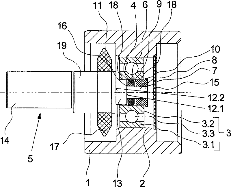
[0021] according to figure 1 The pressure roller of the exemplary embodiment has a hollow-cylindrical roller shell 1 with a hub 2 in the central region. In this embodiment, the roll shell 1 and the hub 2 are designed in one piece. In principle, however, the hub 2 of the roll shell 1 can also be formed from a plurality of individual parts.

[0022] The roller shell 1 is connected in a rotationally fixed manner via a hub 2 to a rolling bearing 3 . For this purpose, the rolling bearing 3 has an outer ring 3 . 1 which is coupled to the hub 2 in a rotationally fixed manner. In addition to the outer ring 3.1, the rolling bearing 3 also includes an inner ring 3.2 and a plurality of rolling elements 3.3 arranged between the outer ring 3.1 and the inner ring 3.2.

[0023] The inner ring 3 . 2 of the rolling bearing 3 is penetrated by the bearing end 7 of the shaft 5 . The bearing end 7 bears an elastic washer 4 . For this purpose, a limiting groove 11 is formed between the shoulde...


PUM


Abstract

The present invention relates to an impression roller which is used for a filament conveying device. The impression roller comprises a shaft and a shaft housing which is rotatably kept on the shaft. Hereon, the shaft housing is connected with a bearing outer ring of a rolling bearing through a mode without relative rotation. The rolling bearing is elastically supported on the shaft through an inner ring and an elastic gasket. According to the invention, for axial stability, the inner ring of the rolling bearing is provided with an annular supporting trough for accommodating the gasket, wherein the gasket is sandwiched between the supporting trough and the shaft.

Description

technical field [0001] The invention relates to a pressure roller for a yarn feeding device according to the preamble of claim 1 . Background technique [0002] Such a pressure roller is known, for example, from WO 2009 / 019110 A1. [0003] In textile machines, yarn conveying devices are used for feeding and stretching the yarns, wherein the yarns are guided on the periphery of drive shafts or drive rollers, which cooperate with abutting pressure rollers. Here, the thread is guided in a nip formed between the pressure roller and the drive shaft. In order to be able to compensate for inaccuracies and alignment errors, the pressure rollers are pivotable so that an axially parallel arrangement is possible. In this case, the pivotability of the pressure roller is achieved by means of a pivot bearing of the roll shell / roller sleeve on the shaft. [0004] A pressure roller is known from WO 2009 / 019110 A1, in which the roller shell is held pivotably on an axle by means of rolling...

Claims


Application Information

Patent Timeline
Patent Type & Authority Applications(China)
IPC IPC(8): B65H51/04B65H51/10F16C27/04F16C33/58
CPCB65H2701/31B65H51/10F16C19/06F16C27/066F16C2340/00
Inventor G・蔡茨H・皮克尔
Owner SAURER TECH GMBH & CO KG
Why Eureka
Try Eureka