Belt transmission cross full shaft type two-degree-of-freedom universal joint mechanism

A technology of belt transmission and universal joints, which is applied in the direction of transmission devices, belts/chains/gears, couplings, etc., can solve the problems of motor reducers being easily damaged and poor load-bearing capacity, and achieve stable bevel gear transmission and improve load-carrying Ability to perform with high precision

Inactive Publication Date: 2011-07-20
HARBIN INST OF TECH
View PDF4 Cites 14 Cited by
  • Summary
  • Abstract
  • Description
  • Claims
  • Application Information

AI Technical Summary

Problems solved by technology

[0003] The purpose of the present invention is to solve the problem that the existing bevel gear differential coupling universal joint mechanism has a rigid contact between the motor reducer and the differential coupling bevel gear, the motor reducer is easily damaged, and the four bevel gears are cantilever mounted. The problem of poor capacity, and then provides a belt-driven cross-axis type two-degree-of-freedom universal joint mechanism

Method used


Image

  • Belt transmission cross full shaft type two-degree-of-freedom universal joint mechanism
  • Belt transmission cross full shaft type two-degree-of-freedom universal joint mechanism
  • Belt transmission cross full shaft type two-degree-of-freedom universal joint mechanism

Examples


specific Embodiment approach 1

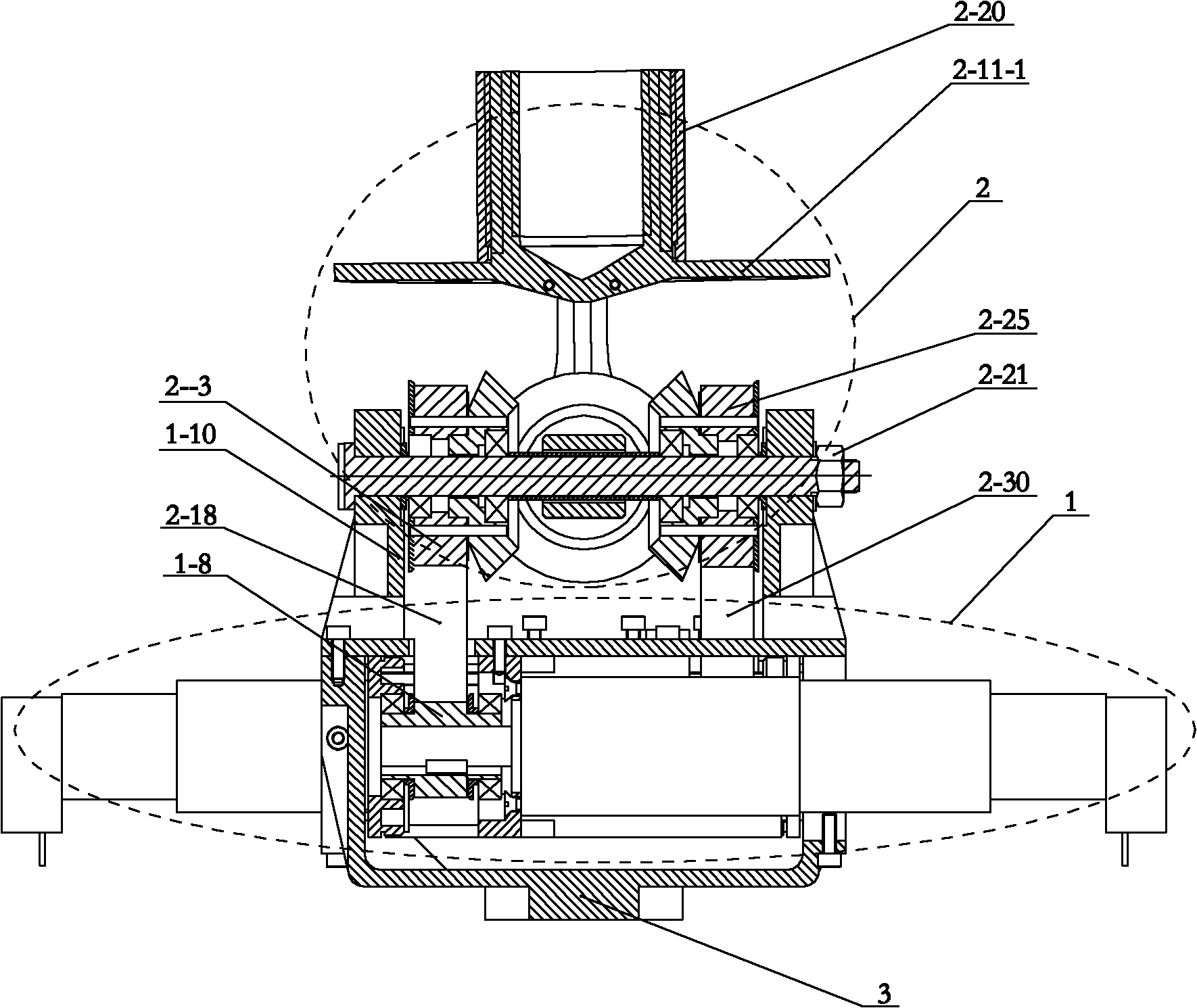
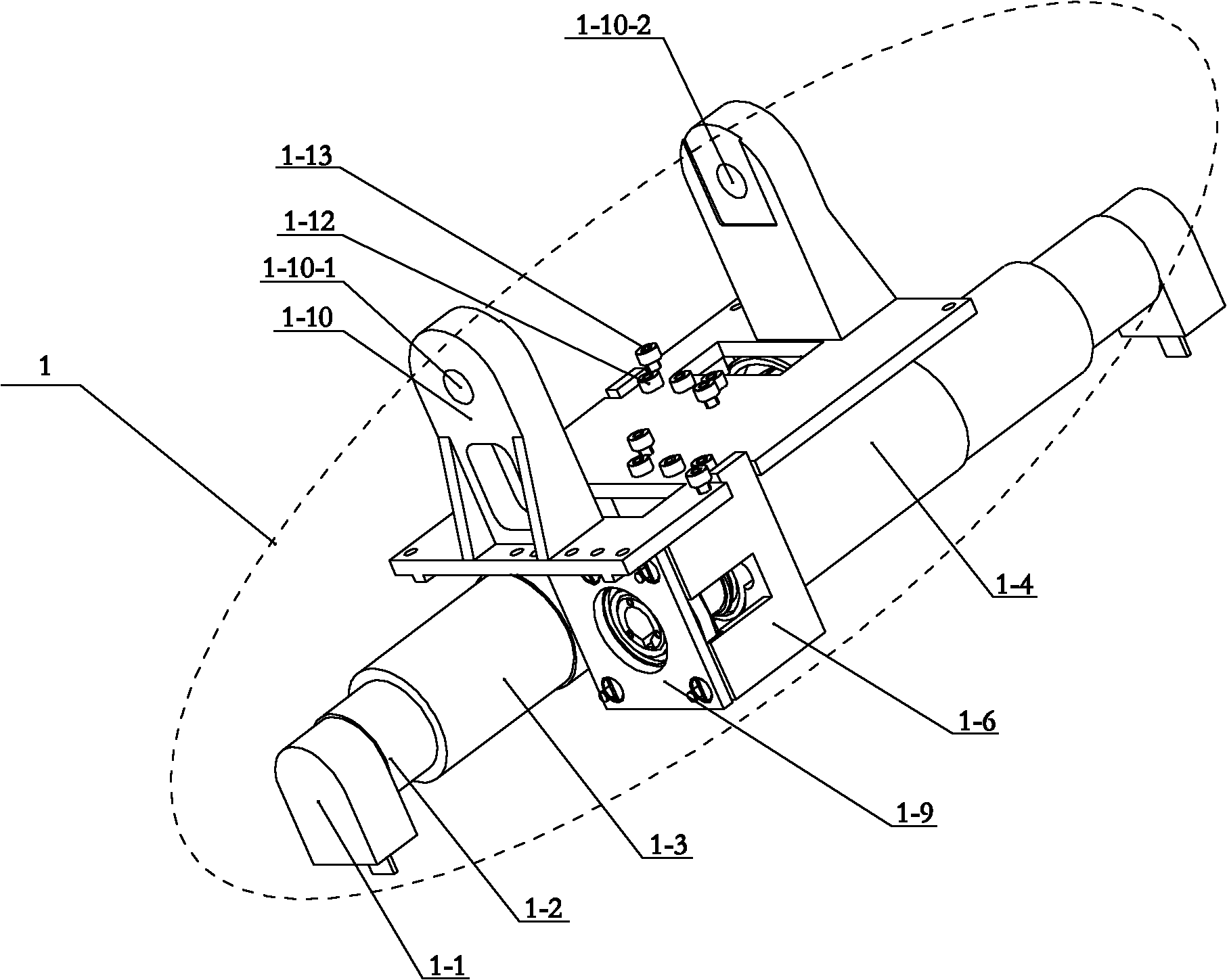
[0013] Specific implementation mode one: as Figure 1-7 As shown, the belt-driven cross full-axis two-degree-of-freedom joint mechanism of this embodiment is composed of a motor drive mechanism 1, a bevel gear differential coupling mechanism 2 and a base 3, and the motor drive mechanism 1 is fixed on the base 3 , the bevel gear differential coupling mechanism 2 is installed on the motor drive mechanism 1; the bevel gear differential coupling mechanism 2 includes a longitudinal axis 2-1, a first large pulley 2-3, a second large pulley 2- 25. The first bevel gear 2-4, the second bevel gear 2-5, the third bevel gear 2-13, the fourth bevel gear 2-16, the first thrust bearing seat 2-6, the second thrust bearing seat 2-26, the first thrust bearing 2-7, the second thrust bearing 2-27, the first limit baffle 2-9, the second limit baffle 2-29, the end platform of the actuator 2-11, Central sleeve 2-14, transverse shaft 2-15, first belt 2-18, second belt 2-30, actuator end sleeve 2-20,...

specific Embodiment approach 2

[0019] Specific implementation mode two: as Figure 6As shown, the first bevel gear 2-4, the second bevel gear 2-5, the third bevel gear 2-13 and the fourth bevel gear 2-16 in this embodiment are all helical bevel gears. With such a design, compared with the straight bevel gear, the helical bevel gear has a higher load capacity, and at the same time, the transmission between the four bevel gears is more stable. Other components and connections are the same as those in the first embodiment.

specific Embodiment approach 3

[0020] Specific implementation mode three: as Figure 7 As shown, the bevel gear differential coupling mechanism 2 in this embodiment also includes four large pulley pins 2-19, and the first large pulley 2-3 and the first bevel gear 2-4 pass through four large pulley pins. Two of the wheel pins 2-19 are fixedly connected, and the third bevel gear 2-13 is fixedly connected to the second large pulley 2-25 through the remaining two of the four large pulley pins 2-19. With such a design, the first large pulley 2-3 can be fixedly connected with the first bevel gear 2-4. Other compositions and connections are the same as those in Embodiment 1 or 2.


PUM


Abstract

The invention discloses a belt transmission cross full shaft type two-degree-of-freedom universal joint mechanism, and relates to a universal joint mechanism, and the mechanism provided by the invention is used for solving the problems of the existing bevel gear differential coupling universal joint mechanism that the rigid contact exists between a motor speed reducer and a differential action coupling bevel gear, the motor speed reducer is easy to damage, four bevel gears are installed in a cantilever mode, and the bearing capability is worse. A horizontal shaft and a vertical shaft are arranged vertically; a first large belt wheel and a first bevel gear as well as a third bevel gear and a second large belt wheel are arranged symmetrically relative to the horizontal shaft; a central sleeve is positioned between the first bevel gear and the third bevel gear; rolling bearings are respectively arranged between the first large belt wheel and the vertical shaft, between the first bevel gear and the vertical shaft, between a third bevel gear and the vertical shaft and between a second large belt wheel and the vertical shaft; the first large belt wheel is fixedly connected with the first bevel gear; the third bevel gear is fixedly connected with the second large belt wheel; two ends of the vertical shaft are installed on two brackets; and the first large belt wheel is correspondingly connected with a small belt wheel in a transmission mode through a first belt. The universal joint mechanism provided by the invention is used for adjusting the posture of the tail end of an actuator.

Description

technical field [0001] The invention relates to a two-degree-of-freedom universal joint mechanism. Background technique [0002] There are two problems in the existing bevel gear differential coupling universal joint mechanism: 1. After the motor passes through the reducer, the torque is transmitted to the differential mechanism composed of four bevel gears through gear meshing. The coupling bevel gears are in rigid contact. If the end of the differential coupling bevel gear is subjected to an impact load, the impact load will damage the motor reducer and cause damage to the function of the universal joint; the second and four differential couplings The bevel gear is installed on the bracket through the half shaft, and the installation method of the four bevel gears is cantilever installation. The bearing capacity of the bevel gear in this structure is poor, and the ability to withstand impact loads is small. The bending of the half shaft will cause the four bevel gears The...

Claims


Application Information

Patent Timeline
Patent Type & Authority Applications(China)
IPC IPC(8): F16D3/16F16H37/08
Inventor 赵志军赵京东刘伊威刘宏谢宗武
Owner HARBIN INST OF TECH
Why Eureka
Try Eureka