

Pressure-reduction type balance hydraulic lock
A hydraulic lock and balance technology, applied to valve details, multi-way valves, engine components, etc., can solve the problems of accidental opening of hydraulic control check valves, poor versatility and flexibility, and high manufacturing costs, so as to prevent load from stalling and dropping, Sensitive movement and strong versatility
- Summary
- Abstract
- Description
- Claims
- Application Information
AI Technical Summary
Problems solved by technology
Method used
Image

Examples
Embodiment 1
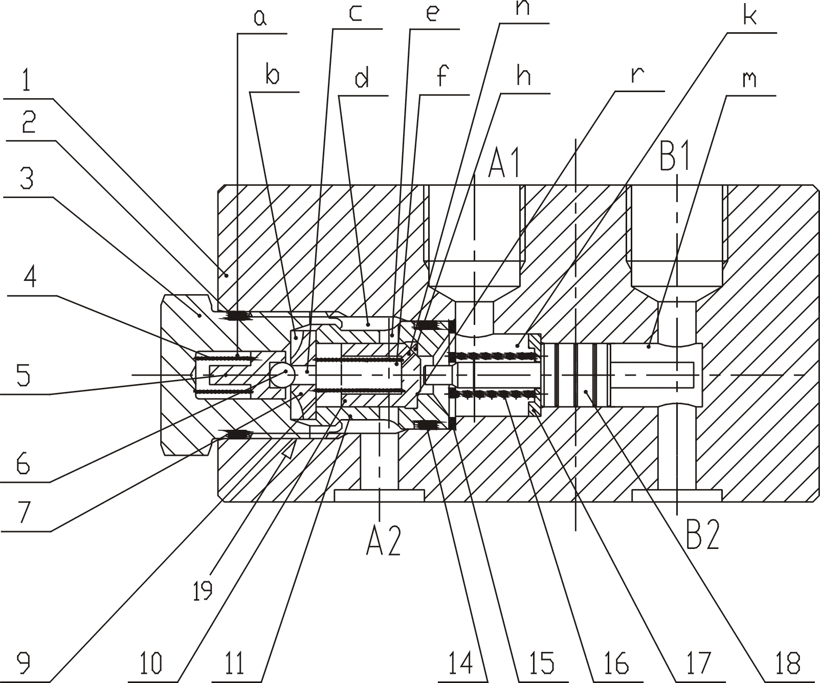
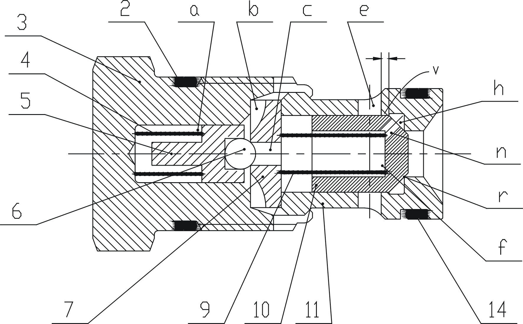
[0027] See Figure 1~3 , this embodiment includes a valve body 1 ( figure 2 shown), the first ferrule 19 ( image 3 shown).
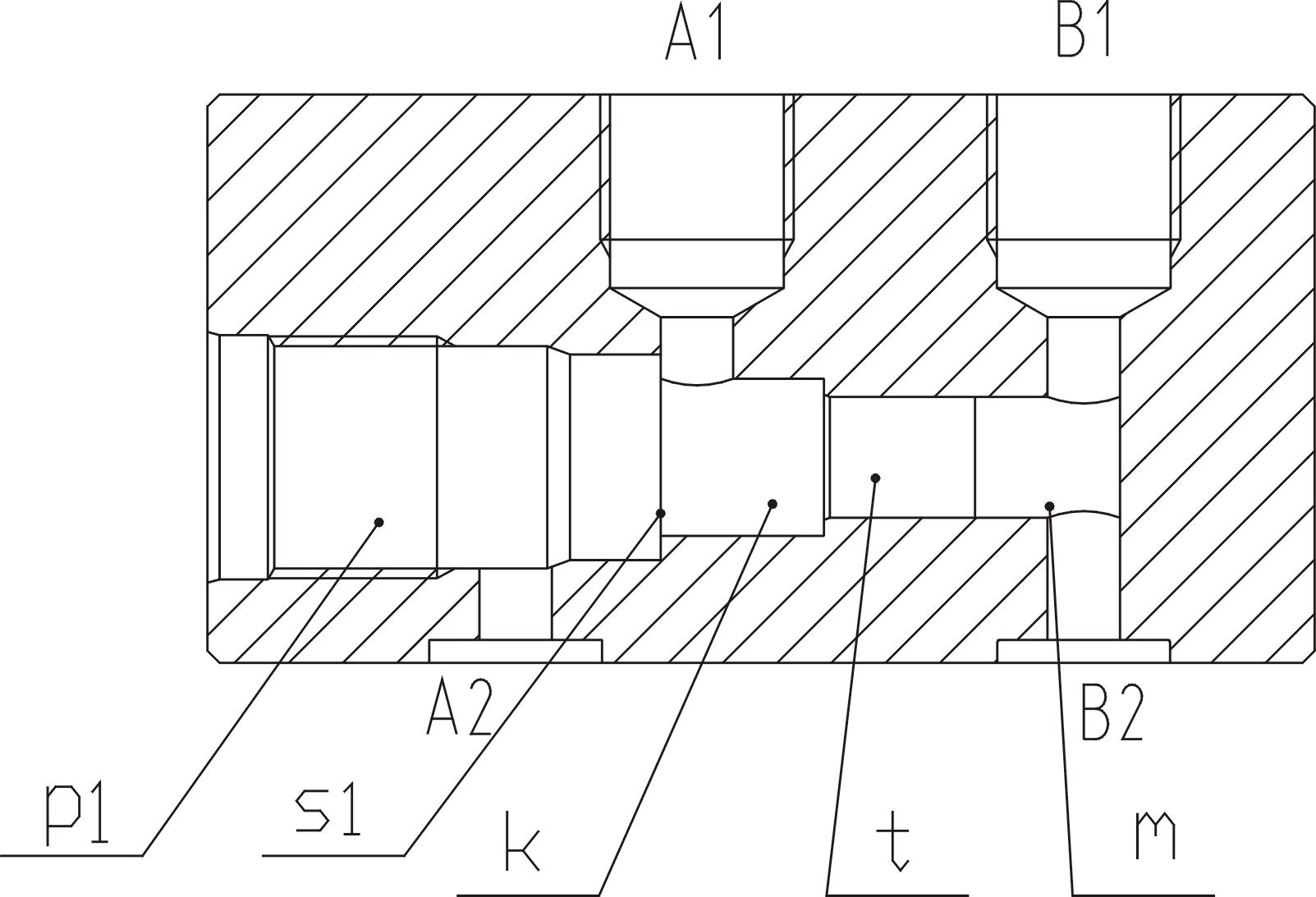
[0028] One end of the valve body 1 is provided with an inner cavity, which is composed of a first insertion hole P1, a first oil chamber K, a control piston installation hole t, and a second oil chamber m from left to right.
[0029] See figure 1 , 2 , the first oil port A1 communicates with the first oil chamber K, the second oil port A2 communicates with the first insertion hole P1, the third oil port B1 and the fourth oil port B2 communicate with the second oil chamber m respectively.
[0030] See figure 1 , 2 , the first ferrule 19 is installed in the first insertion hole P1; the first porous plate 15 is pressed by the first ferrule 19 on the first positioning end surface S1 of the valve body 1 (see the first positioning end surface S1 figure 2 ).
[0031] The control piston 18 is installed in the control piston installation hole t, and th...
Embodiment 2
[0044] See figure 2 , 4 , 5, the valve body 1 in this embodiment is the same as the valve body in Embodiment 1, the difference is that: the first ferrule 19 also includes a fourth spring 8, a spring guide rod 12, a pressure relief valve 13 , Pressure relief hole j. Wherein, the pressure relief hole j is arranged in the middle of the front end of the main valve core 10, and the pressure relief valve 13, the spring guide rod 12 and the fourth spring 8 are arranged at the rear end of the pressure relief hole j; the fourth spring 8 compresses the pressure relief valve 13 On the pressure relief hole j.
[0045] In this embodiment, the pressure relief valve 13 is first opened to release the pressure in the fourth oil chamber f, and then the main valve core 10 is opened. However, in Embodiment 1, the main valve core 10 is first opened to release pressure from the fourth oil chamber f through the orifice n. Because the pressure receiving area of the pressure relief valve 13 is ...
Embodiment 3
[0051] See Figure 6 , 7 , and see image 3 The first ferrule, the first ferrule in this embodiment is the same as the first ferrule in Embodiment 1.
[0052] The difference between this embodiment and Embodiment 1 is that the front end of the second oil chamber m is also connected with a second insertion hole P2 with the same structure as the first insertion hole P1, and a second ferrule with the same structure as the first ferrule 19 20 is installed in the second insertion hole P2; the second perforated plate 155 is pressed against the second positioning end surface S2 of the valve body 1 by the second ferrule 20 . A second limit pad 177 is arranged at the front end of the control piston 18 . The fifth spring 166 is installed between the second limiting pad 177 and the second perforated plate 155 , and the fourth oil port B2 communicates with the second insertion hole P2 .
[0053] Embodiment 1 can only control one chamber of the oil cylinder, and can only control the ru...
PUM
 Abstract
Description
Claims
Application Information