Device and method for hoop tensile test based on laser impact biaxial loading

A bidirectional loading and hoop stretching technology, applied to measuring devices, instruments, scientific instruments, etc., can solve problems such as high risk, many influencing factors, and difficult control, achieving large energy and strain rate, simple loading process, The effect of few influencing factors

Inactive Publication Date: 2011-07-20
JIANGSU UNIV
View PDF2 Cites 10 Cited by
  • Summary
  • Abstract
  • Description
  • Claims
  • Application Information

AI Technical Summary

Problems solved by technology

[0003] Among them, the expansion ring technology is an important technology for one-dimensional high strain rate tensile loading to measure the dynamic properties of materials, and the traditional loading methods of the expansion ring technology are mainly through block impact, explosive detonation and electromagnetic drive. Larger, difficult to co...

Method used


Image

  • Device and method for hoop tensile test based on laser impact biaxial loading
  • Device and method for hoop tensile test based on laser impact biaxial loading
  • Device and method for hoop tensile test based on laser impact biaxial loading

Examples


Embodiment Construction

[0032] The present invention will be further described in detail below in conjunction with the accompanying drawings and embodiments.

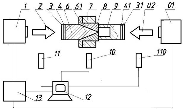
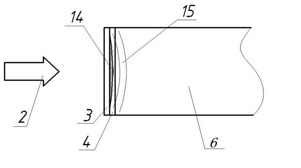
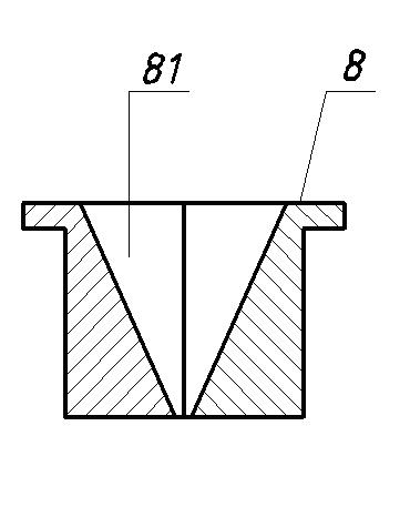
[0033] Such as figure 1 Shown, a kind of impact tensile test method and device loaded by laser shock, including 1. laser head A, 01 laser head B, 2. laser pulse A, 02. laser pulse B, 3. constrained layer A, 31. Constraining layer B, 4. Absorbing layer A, 41. Absorbing layer B, 6. Loading rod A, 61 cone, 7. Ring specimen, 8. Cylindrical driving ring, 81. Conical hole, 82. Driving block A, 83. Drive block B, 84. Drive block C, 9 Load rod B., 10. Laser interferometer, 11. Trigger A, 110. Trigger B, 12. Computer, 13. High power pulsed laser, load rod 6 The other end of the cylindrical drive ring 8 is provided with a cone 61. The cylindrical drive ring 8 is composed of three separate drive blocks A82, drive block B83 and drive block C84. One end of the cylindrical drive ring 8 is provided with a The other end of the cylindrical driving ring 8 is ...


PUM

PropertyMeasurementUnit
Pulse widthaaaaaaaaaa
Wavelengthaaaaaaaaaa

Abstract

The invention relates to a material dynamic tensile mechanical property test and belongs to the technical field of a material dynamic tensile mechanical property test. By using an intense laser pulse-induced impact wave as a loading condition, the material achieves a high strain rate; and different strain rates can be loaded by changing the laser pulse width and laser energy. A device comprises ahigh-power pulse laser (13), a laser head A (1), a laser head B (01), a restraining layer A (3), a restraining layer B (31), an absorbing layer A (4), an absorbing layer B (41), a loading rod A (6), a loading rod B (9), a cylindrical driving ring (8), a laser interferometer (10), a trigger A (11), a trigger B (110) and a computer (12). The device provided by the invention can be used for researching the dynamic tensile property of the material under the condition of different strain rates. The loading process is simple, the influencing factors are few, the calculation process is simple and the test cost is low.

Description

technical field [0001] The invention relates to the technical field of material dynamic tensile mechanical performance testing, in particular to a method and device for testing hoop tensile performance of materials loaded by laser shock. Background technique [0002] In a series of practical problems in a wide range of fields such as engineering technology, military technology and scientific research, and even in daily life, people will encounter various problems of explosions and impact loads, and it can be observed that objects in The mechanical responses under explosion and impact loads are often significantly different from those under static loads. Understanding the mechanical responses of materials under impact loading conditions will greatly contribute to the engineering applications and engineering designs of these materials. In addition, numerical simulation has played an important role in engineering design, and the premise of numerical simulation must first establ...

Claims


Application Information

Patent Timeline
IPC IPC(8): G01N3/313
Inventor 张永康姜银方钱晓明姜文帆何玉中黄勤
Owner JIANGSU UNIV
Why Eureka
Try Eureka