Supercharge Your Innovation With Domain-Expert AI Agents!

Micro-mirror device screening method, micro-mirror device screening device and no-mask exposure device

A technology of a micromirror device and a screening method, which is applied in the photoplate-making process exposure device, microlithography exposure equipment, optics, etc.

Inactive Publication Date: 2013-12-18
HITACHI HIGH-TECH CORP
View PDF1 Cites 0 Cited by
  • Summary
  • Abstract
  • Description
  • Claims
  • Application Information

AI Technical Summary

Problems solved by technology

Masks are used for exposure, but when developing new display devices, the delivery time of masks becomes a bottleneck in short-term development

Method used


Image

  • Micro-mirror device screening method, micro-mirror device screening device and no-mask exposure device
  • Micro-mirror device screening method, micro-mirror device screening device and no-mask exposure device
  • Micro-mirror device screening method, micro-mirror device screening device and no-mask exposure device

Examples


Embodiment approach 1

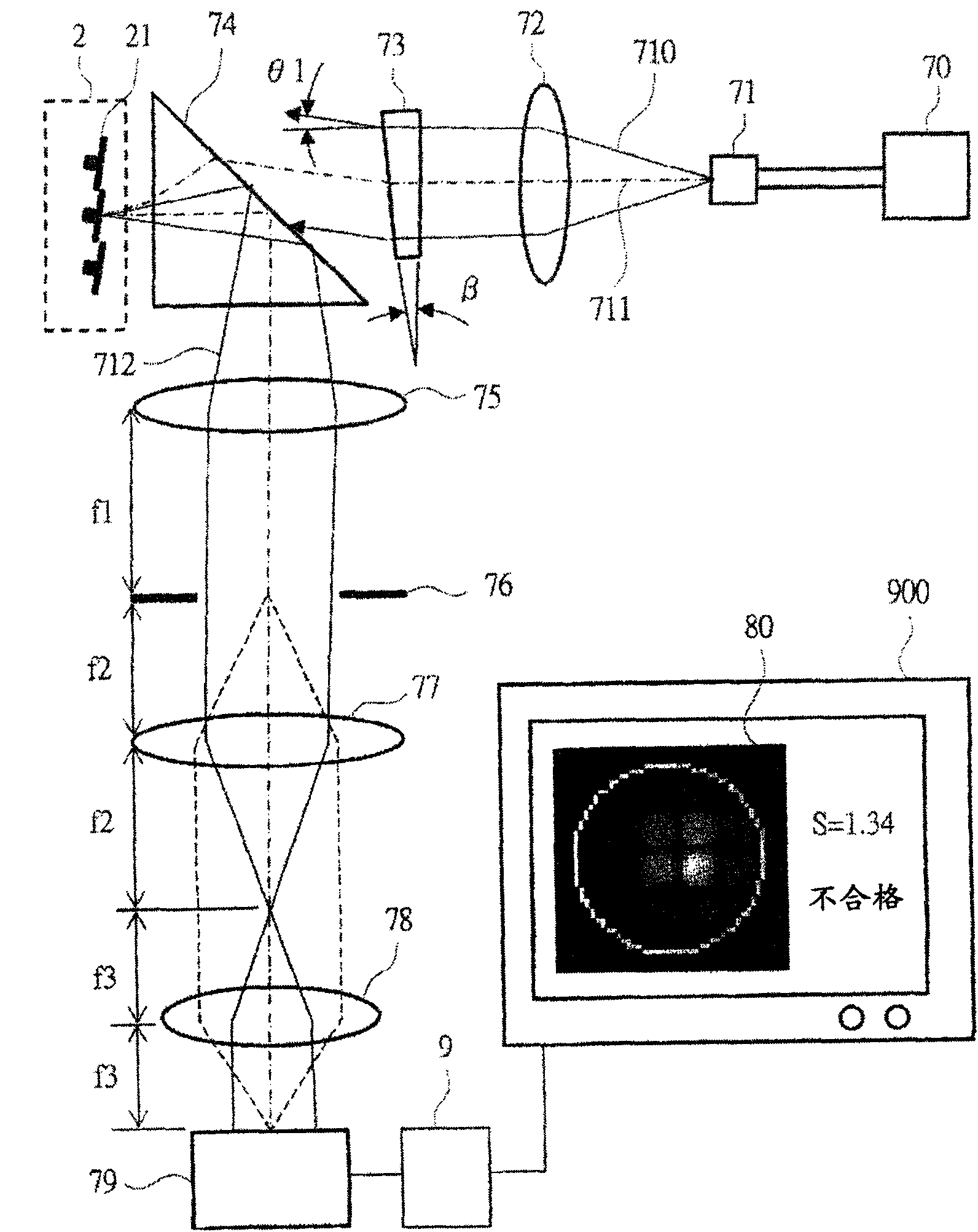
[0059] pass figure 1 The configuration of a micromirror device (hereinafter referred to as MMD) screening device according to Embodiment 1 of the present invention will be described. figure 1 It is a configuration diagram showing the configuration of the MMD screening device according to the embodiment of the present invention.

[0060] exist figure 1 Among them, the MMD screening device consists of MMD2, processing section 9, illumination system, i.e. light source 70 and optical fiber 71, collimating lens 72 as optical system, wedge-shaped glass 73, rectangular prism 74, lenses 75, 77, 78 and aperture 76, imaging element 79. The display system 900 is configured. The MMD2 is composed of a micromirror 21 .

[0061] In this embodiment, the MMD2 is irradiated with parallel light at a predetermined angle, and the reflected light is parallel-corrected through the lens, and the diffracted light distribution is shrunk and imaged on the imaging element through the lens system, a...

Embodiment approach 2

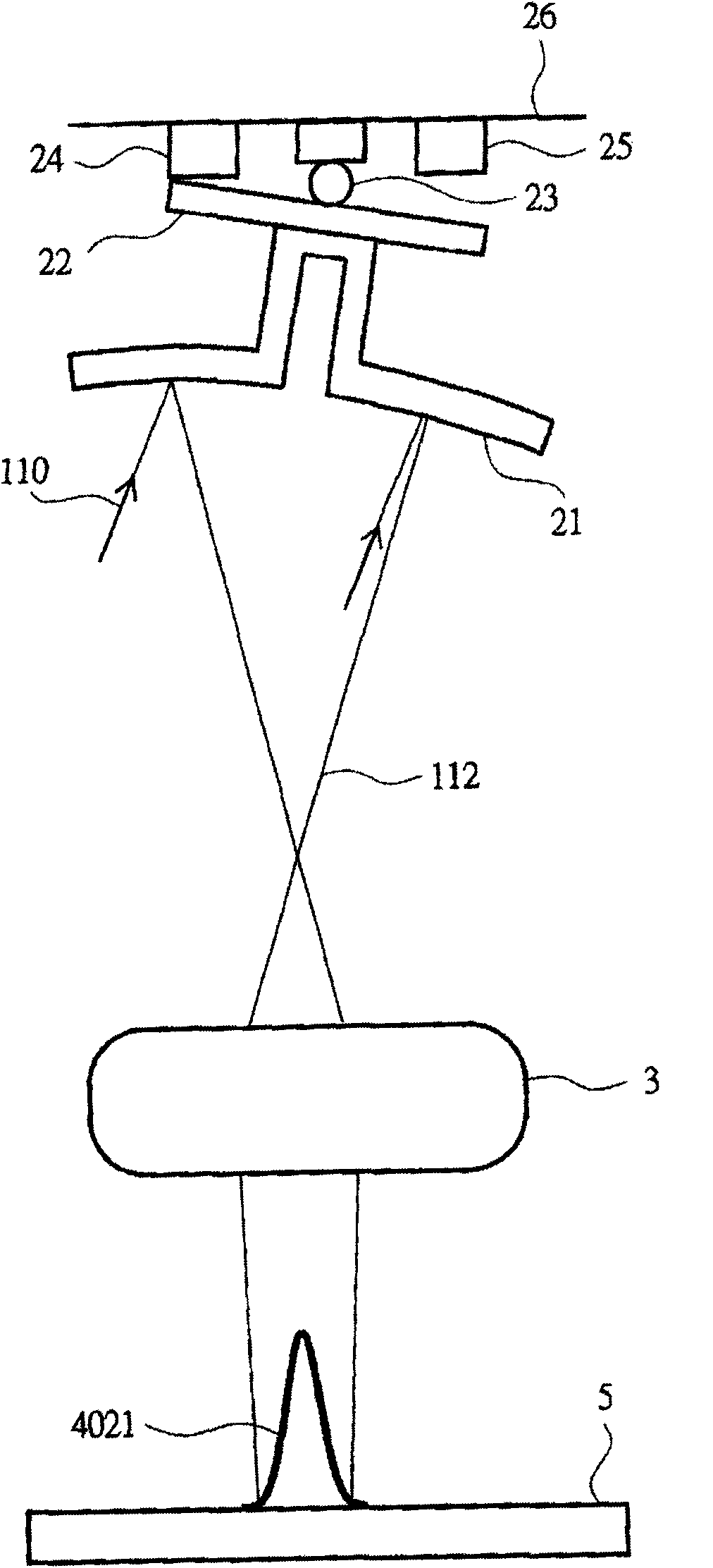
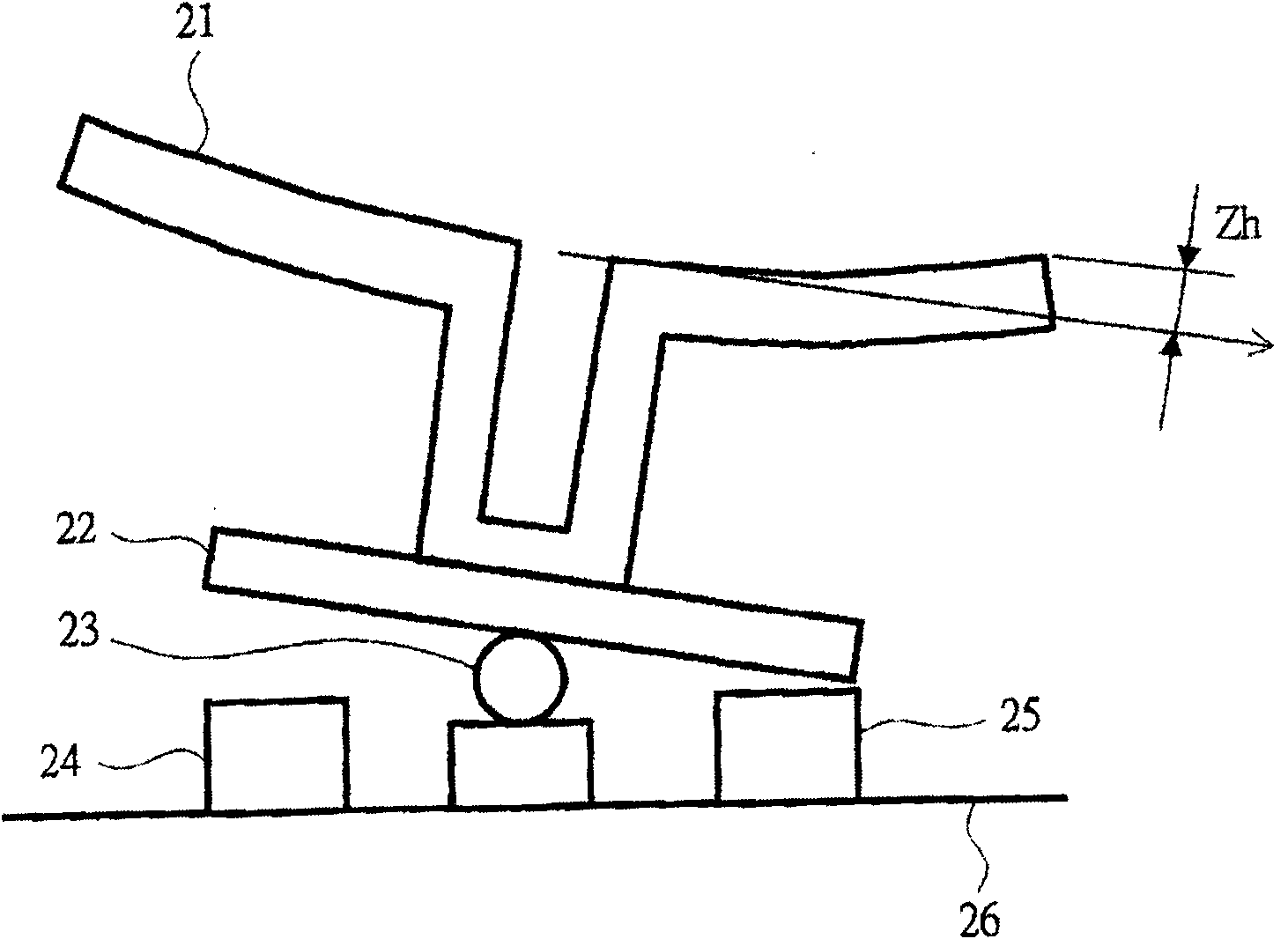
[0098] This embodiment is a form in which the MMD screening apparatus of Embodiment 1 is mounted on a maskless exposure apparatus.

[0099] pass Figure 9 and Figure 10 The structure and operation of the maskless exposure apparatus according to Embodiment 2 of the present invention will be described. Figure 9 is a configuration diagram showing the configuration of a maskless exposure apparatus according to Embodiment 2 of the present invention, Figure 10 It is a diagram of the rotary aperture of the illumination system of the maskless exposure apparatus according to Embodiment 2 of the present invention.

[0100] In this embodiment, the diffracted light distribution is monitored on a maskless exposure apparatus.

[0101] exist Figure 9 In, maskless exposure setup with figure 1 The shown MMD screening device is the same, has: MMD2, processing system 9, light source 70, optical fiber 71, collimating lens 72, wedge-shaped glass 73, rectangular prism 74, lens 75,77,78, a...


PUM


Abstract

The present invention provides a micro-mirror screening method, a micro-mirror device screening device and a no-mask exposure device. The micro-mirror screening device is used for obtaining a portrayed pattern which has no dent part in a width direction and a thickness direction and has excellent linearity. The micro-mirror device screening device is provided with the following components: an irradiation system which irradiates illumination light to the micro-mirror device (2); an optical system which causes the diffracted light generated through the micro-mirror (21) to incident into an image pickup component (79); and a processing system (9) which determines whether the micro-mirror device (2) is qualified through processing a diffracted light distribution image that is picked by the image pickup device (79).

Description

technical field [0001] The present invention relates to a method for screening micromirror devices and a screening device for micromirror devices equipped in a maskless exposure device for replicating firing patterns on a panel or a semiconductor mask for display equipment, in particular to the micromirrors of micromirror devices Flatness detection. Background technique [0002] Panels such as liquid crystal or organic EL (electroluminescence) are manufactured by printing the circuit pattern drawn on the mask on the substrate. As a process, a photoresist is applied after depositing a thin film on a glass substrate, and a circuit pattern is exposed and developed. Then, the underlying thin film is etched through the photoresist pattern to form a thin film pattern. By repeating this process multiple times to laminate thin film patterns, a circuit pattern capable of controlling the brightness of each pixel is produced. [0003] In order to perform color display, a color filte...

Claims


Application Information

Patent Timeline
Patent Type & Authority Patents(China)
IPC IPC(8): G03F7/20
CPCB07C5/342G01M11/02G03F7/2051G03F7/70058G03F7/70125G03F7/7015G03F7/702G03F7/70383G03F7/70558G03F7/70833
Inventor 吉武康裕根本亮二上野刚渡
Owner HITACHI HIGH-TECH CORP
Features
  • R&D
  • Intellectual Property
  • Life Sciences
  • Materials
  • Tech Scout
  • Unparalleled Data Quality
  • Higher Quality Content
  • 60% Fewer Hallucinations
Learn More